- 您現在的位置:買賣IC網 > Datasheet目錄40 > IXCY60M35 (IXYS)IC CURRENT REGULATOR DPAK Datasheet資料下載
參數資料
| 型號: | IXCY60M35 |
| 廠商: | IXYS |
| 文件頁數: | 3/3頁 |
| 文件大小: | 552K |
| 描述: | IC CURRENT REGULATOR DPAK |
| 產品變化通告: | AC/DC Regulator Discontinuation 28/Jul/2004 |
| 標準包裝: | 50 |
| 系列: | IXC |
| 功能: | 穩流器 |
| 電流 - 輸出: | 60mA |
| 工作溫度: | -55°C ~ 150°C |
| 安裝類型: | 表面貼裝 |
| 封裝/外殼: | TO-252-3,DPak(2 引線+接片),SC-63 |
| 供應商設備封裝: | TO-252AA |
| 包裝: | 管件 |
3
Application Examples
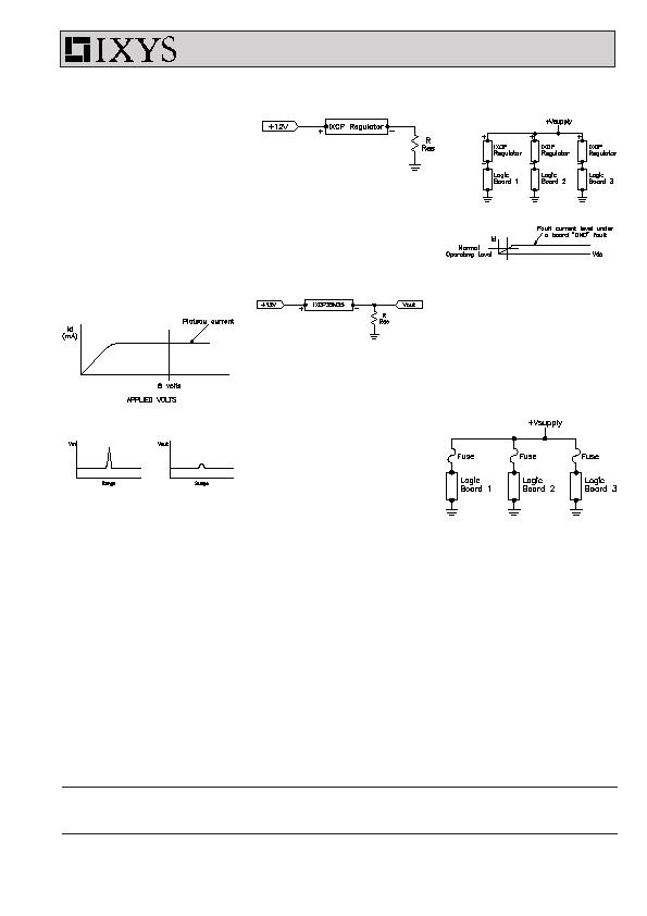
DC and AC Overvoltage
Suppression
The regulator can be used as a
voltage surge suppressor. The device
is again connected in series with the
lead (Fig. 5) and would normally
operate at a current level lower than
the plateau (Fig. 6a). Any incoming
voltage surge (Fig. 6b) less than the
breakdown voltage of the regulator will
be clamped by the IXCP regulator to
voltage less than the plateau current
times the effective resistance of the
load.
Testing & Handling
Recommendations
For initial assessment of the parts
where the customer may test the
device characteristics in free air
without heat sinking, the continuous
power dissipation should be kept
within 1.5 W at ambient of 25
?/DIV>
C.
(R
thJA
= 80 K/W for TO-220, and
R
thJA
= 100 K/W for TO-252)
Normal electrostatic handling
precautions for MOS devices
should be adhered to.
Fig. 5. DC surge suppression
Soft Start-Up Circuits
Here the regulator characteristic will
clamp initial current surges which can
occur when power is initially applied
to a load. The device, with its 450 V
capability could, for example, be used
with a DC power supply or with AC
mains to limit the initial high inrush of
current into lamp filaments, thereby
increasing the filament life several
times. It could, therefore, be used
effectively in lighting displays and in
the transportation lighting industries.
Highly Stable Voltage Sources
Another obvious application would be
to use the current regulator as a
Fig. 9. Normal fusing links in
series with each board
Fig.8. Low cost current regulators
instead of fuses
Fig. 6b. Incoming surge/output surge
across load
Fig. 6a. DC surge suppression
source of a highly stable current to
produce a usable voltage reference
(Fig. 7). This would be effectively
independent of temperature and a low
cost approach. A high voltage
reference is also possible, thanks to
their high breakdown voltages.
Instantaneous "Fuse"
Another application would be
protection against sudden voltage
droops on voltage supply lines to logic
cards in computing systems, resulting
from one component suddenly
shorting to ground. Normal fusing
networks will draw considerable
current during the time it takes for the
fuse to clear. This could cause a
sufficient dip in power rail voltage to
cause malfunctions of the other logic
cards, even with fast-blow fuses (Fig.
8). The current regulator in series with
the logic card restricts the current to
its own operating level (Fig. 9).
Therefore the voltage supply does not
become overloaded and the regulator
remains intact.
The current regulator thus provides an
"instantaneous fusing" function. When
the logic component is replaced, the
regulator resumes its normal
functioning mode.
The obvious advantages to having this
regulator as fuse substitute are:
Prevents a "dip" in the power
supply during a fault condition
Regulator remains intact
Can be easily tied in with logic to
indicate a "down state" board
R = 100 & V
out
= 3.5 V nominal
R = 50 &
V
out
= 1.75 V nominal
R = 25 &
V
out
= 0.875 V nominal
Fig. 7. Simple voltage source with
high stability
IXC Series
IXYS MOSFETs and IGBTs are covered by 4,835,592 4,931,844
5,049,961
5,237,481
6,162,665
6,404,065 B1 6,683,344
6,727,585
one or moreof the following U.S. patents: 4,850,072 5,017,508
5,063,307
5,381,025
6,259,123 B1
6,534,343
6,710,405B2 6,759,692
4,881,106 5,034,796
5,187,117
5,486,715
6,306,728 B1
6,583,505
6,710,463
相關PDF資料 |
PDF描述 |
|---|---|
| IXI848S1 | IC CURRENT MONITOR 0.7% 8SOIC |
| KA331 | IC CONVERTER VOLT TO FREQ 8-DIP |
| LDS9003-002-T2 | IC TEMP/PWM CONTROLLER 16WQFN |
| LM334Z#PBF | IC CURRENT SOURCE TO92-3 |
| LM75AD,112 | IC TEMP SENSOR DIGITAL 8-SOIC |
相關代理商/技術參數 |
參數描述 |
|---|---|
| IXCY60M45 | 功能描述:電流和電力監控器、調節器 0.06 Amps 450V RoHS:否 制造商:STMicroelectronics 產品:Current Regulators 電源電壓-最大:48 V 電源電壓-最小:5.5 V 工作溫度范圍:- 40 C to + 150 C 安裝風格:SMD/SMT 封裝 / 箱體:HPSO-8 封裝:Reel |
| IXD_602 | 制造商:CLARE 制造商全稱:Clare, Inc. 功能描述:2-Ampere Dual Low-Side Ultrafast MOSFET Drivers |
| IXD_604 | 制造商:CLARE 制造商全稱:Clare, Inc. 功能描述:4-Ampere Dual Low-Side Ultrafast MOSFET Drivers |
| IXD_609 | 制造商:CLARE 制造商全稱:Clare, Inc. 功能描述:9-Ampere Low-Side Ultrafast MOSFET Drivers |
| IXD_614 | 制造商:CLARE 制造商全稱:Clare, Inc. 功能描述:14-Ampere Low-Side Ultrafast MOSFET Drivers |
發布緊急采購,3分鐘左右您將得到回復。