- 您現(xiàn)在的位置:買賣IC網(wǎng) > PDF目錄366079 > 1393267-6 (Tyco Electronics) Automotive Relays PDF資料下載
參數(shù)資料
| 型號(hào): | 1393267-6 |
| 廠商: | Tyco Electronics |
| 元件分類: | 特殊繼電器 |
| 英文描述: | Automotive Relays |
| 中文描述: | 汽車?yán)^電器 |
| 文件頁數(shù): | 1/3頁 |
| 文件大小: | 373K |
| 代理商: | 1393267-6 |
01-2012, Rev. 0112
www.te.com
2011 Tyco Electronics Corporation,
a TE Connectivity Ltd. company.
Datasheets and product specification ac-
cording to IEC 61810-1 and to be used only
together with the ‘Definitions’ section.
Datasheets and product data is subject to the
terms of the disclaimer and all chapters of
the ‘Definitions’ section, available at
http://relays.te.com/definitions
Datasheets, product data, ‘Definitions’ sec-
tion, application notes and all specifications
are subject to change.
1
n
Limiting continuous current 30 A
Typical applications
Car alarm, door control, door lock, immobilizer, seat control, sun roof,
window lifter, wiper control.
Contact Data
Contact arrangement
Rated voltage
Rated current
Limiting continuous current
at 23°C
at 85°C
Limiting making current
1)
35A
Limiting breaking current
1)
35A
Contact material
Min. recommended contact load
Initial voltage drop at 10A, typ./max.
Operate/release time max. at nominal voltage typ. 3 /1.3ms
4)
Electrical endurance
at cyclic temperature -40/+23/+85°C and 13.5VDC,
both systems AgNi0.15, motor reverse blocked,
25A, 0.77mH inductive
AgSnO
2
, lamp load, 45A (on), 8A (off), 80°C >2x10
5
ops.
AgSnO
, resistive load, 20A, 80°C
Mechanical endurance
1) The values apply to a resistive or inductive load with suitable spark suppression and at
maximum 13.5VDC for 12VDC load voltages.
2) At 50% ON period: max. make time 15s.
3) See chapter Diagnostics of Relays in our Application Notes or consult the internet at
http://relays.te.com/appnotes/
4) For unsuppressed relay coil. A low resistive suppression device in parallel to the relay
coil increases the release time and reduces the lifetime caused by increased erosion
and/or higher risk of contact tack welding.
2 form C, 2 CO
12VDC
both
systems
18/18A
both
systems
20/20A
motor
reverse
1)2)
30/30A
motor
reverse
1)2)
30/30A
20/20A
15/15A
30/30A
2)
30/30A
35A
35A
AgNi0.15
18/18A
12/12A
35A
35A
AgSnO
2
1A at 5VDC
3)
30/300mV
30/30A
2)
30/30A
35A
35A
AgSnO
2
AgNi0.15
>10
5
ops.
>2x10
5
ops.
>10
7
operations
Coil Data
Coil voltage range
Rated coil voltage
-40 to +85°C
12VDC
Coil versions, DC coil
Coil
code
001
002
All figures are given for coil without pre-energization, at ambient temperature +23°C.
Rated
voltage
VDC
12
12
Operate
voltage
VDC
6.9
5.8
Release
voltage
VDC
1.0
0.8
Coil
Rated coil
power
mW
565
809
resistance
±10%
255
178
Double Mini Relay DMR
Automotive Relays
PCB Double Relays
0
0
10
20
30
40
ECR2221-D
50
60
10
20
30
40
50
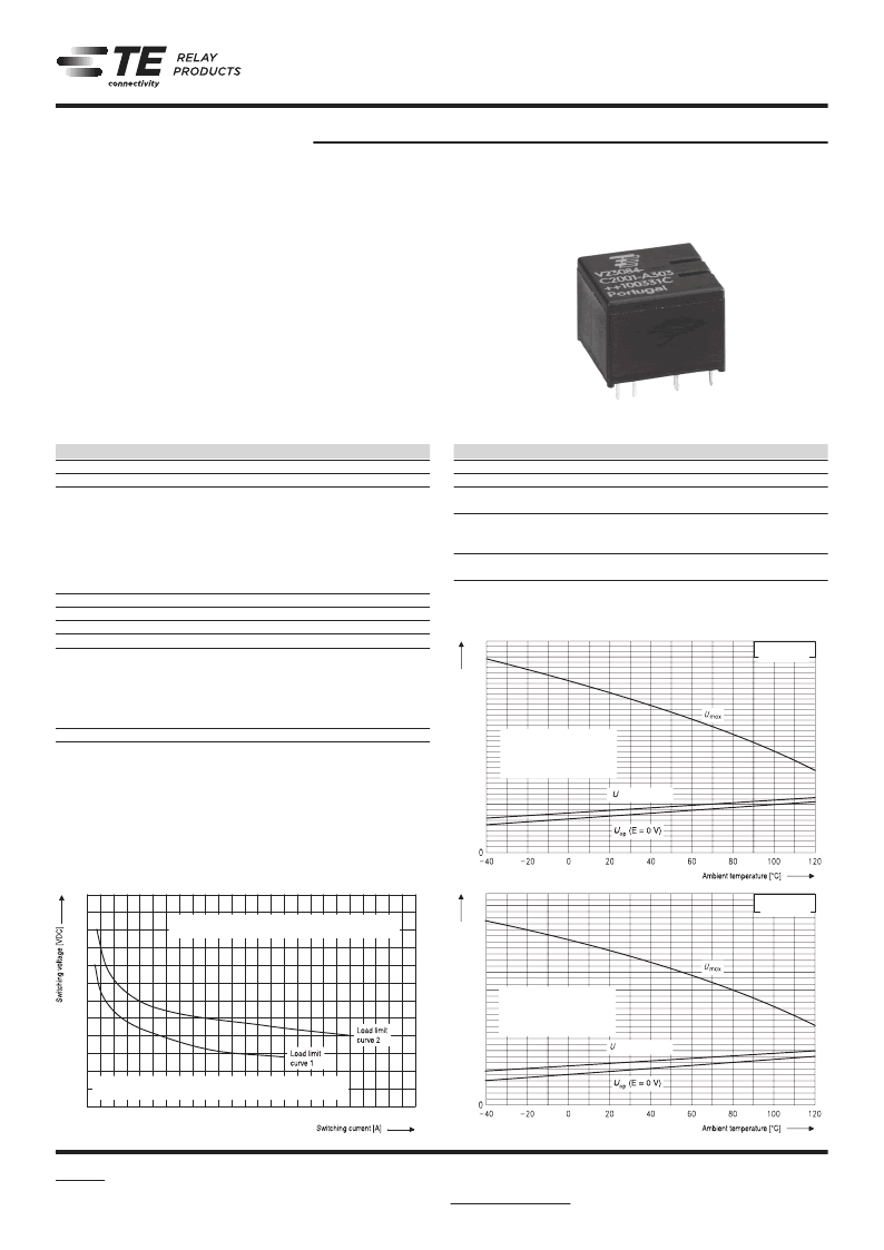
Load limit curve 1: arc extinguishes during transit time
Load limit curve 2: safe shutdown, no stationary arc
Max. DC load breaking capacity
Load limit curves measured with low inductive resistors
verified for 1000 switching events.
Does not take into account
the temperature rise due to
the contact current
E = pre-energization
ECR2226-J
35
5
10
15
20
25
C
30
Coil 002
op
(E = 13.5 V)
Does not take into account
the temperature rise due to
the contact current
E = pre-energization
ECR2225-B
40
35
5
10
15
20
25
C
30
Coil 001
op
(E = 13.5 V)
Coil operating range
Does not take into account
the temperature rise due to
the contact current
E = pre-energization
Does not take into account
the temperature rise due to
the contact current
E = pre-energization
F084_fcw2c_bw
相關(guān)PDF資料 |
PDF描述 |
|---|---|
| 1393276-3 | Automotive Relays |
| 1393276-7 | Automotive Relays |
| 13HC | Hook-Up Wire; Conductor Size AWG:28; No. Strands x Strand Size:Solid; Jacket Color:Orange; Approval Bodies:UL, CSA; Approval Categories:UL AWM Style 1061; CSA AWM; Conductor Material:Copper; Conductor Plating:Tin RoHS Compliant: Yes |
| 13HCA | Hook-Up Wire; Conductor Size AWG:28; No. Strands x Strand Size:Solid; Jacket Color:Yellow; Approval Bodies:UL, CSA; Approval Categories:UL AWM Style 1061; CSA AWM; Conductor Material:Copper; Jacket Material:Polyvinylchloride (PVC) RoHS Compliant: Yes |
| 13HCB | Hook-Up Wire; Conductor Size AWG:28; No. Strands x Strand Size:Solid; Jacket Color:Yellow; Approval Bodies:UL, CSA; Approval Categories:UL AWM Style 1061; CSA AWM; Conductor Material:Copper; Jacket Material:Polyvinylchloride (PVC) RoHS Compliant: Yes |
相關(guān)代理商/技術(shù)參數(shù) |
參數(shù)描述 |
|---|---|
| 1393270-1 | 制造商:TE Connectivity 功能描述: |
| 1393270-6 | 制造商:TE Connectivity / AMP 功能描述: |
| 1393270-9 | 制造商:TE Connectivity 功能描述: |
| 1393273-2 | 制造商:TE Connectivity 功能描述: |
| 1393273-9 | 制造商:TE Connectivity 功能描述: |
發(fā)布緊急采購,3分鐘左右您將得到回復(fù)。