- 您現(xiàn)在的位置:買賣IC網(wǎng) > PDF目錄366079 > 1423089-1 (Tyco Electronics) Mid–Range PC Board Relays PDF資料下載
參數(shù)資料
| 型號: | 1423089-1 |
| 廠商: | Tyco Electronics |
| 元件分類: | 特殊繼電器 |
| 英文描述: | Mid–Range PC Board Relays |
| 中文描述: | 中等功率PC板繼電器 |
| 文件頁數(shù): | 1/2頁 |
| 文件大小: | 83K |
| 代理商: | 1423089-1 |
414
Dimensions are shown for
reference purposes only.
Dimensions are in inches over
(mllimeters) unless otherwise
specified.
Specifications and availability
subject to change.
P&B
Catalog 1308242
Issued 3-03 (PDF Revised 8-06)
www.tycoelectronics.com
Technical support:
Refer to inside back cover.
File E29244
File No. 3919
Sensitive, Low Profile, Hi-Current
Relay Designed to Meet
International Standards
Mechanical Data
Termination:
Printed circuit terminals.
Enclosures:
Wash tight (washable) case.
Weight:
0.39 oz. (11.0g) approximately.
Initial Dielectric Strength
Between Open Contacts:
1,000V rms.
Between Contacts and Coil:
4,000V rms, 8mm.
T75
series
10 Amp, PC Board
Miniature Relay
Coil Data
Voltage:
3 to 60VDC.
Maximum Power @ 23
°
C:
1W.
Nominal Power @ 23
°
C:
230mW, typ.
Temperature Rise:
85C
°
per Watt.
Duty Cycle:
Continuous.
Operate Data @ 23
°
C
Must Operate Voltage:
70% of nom. voltage or less.
Must Release Voltage:
10% of nom. voltage or more.
Operate Time (Excluding Bounce):
6 ms, typ., at nom. voltage.
Release Time (Excluding Bounce):
2.5 ms, typ., at nom. voltage.
Maximum Switching Rate:
20 operations/second.
Maximum Continuous Operating Voltage:
225% of nom. voltage.
Coil Data
Features
High sensitivity – nominal coil power requirement is as low as 212mW.
Low profile, .591 in. (15mm) tall case uses only .465 in
2
(3cm
2
) of area on the
printed circuit board, permitting high density circuit design.
Power switching capability – contacts rated 10 amps in 1 Form A (SPST-NO) or 1
Form C (SPDT) arrangements.
Designed to meet UL, CSA, VDE, SEMKO and SEV requirements.
Designed to meet VDE 8mm spacing, 4kV dielectric, coil to contacts.
Designed to meet 3 mm creepage between contacts.
Conforms to:
VDE 0110 – Insulation Group C (250V)
VDE 435 Part 201 – High current applications
VDE 0804 – Telecommunications equipment
VDE 0631 – Temperature controllers and limiters
VDE 0700 – Household appliances
VDE 0805/5.90 – Office machines
Wash tight (washable).
Well suited for a broad range of applications e.g. HVAC, appliances,
security and industrial control.
Contact Ratings @ 25
°
C with relay properly vented.
Remove vent nib after soldering and cleaning.
Arrangements:
1 Form A (SPST-NO) and 1 Form C (SPDT).
Material:
Silver-cadmium oxide.
Expected Mechanical Life:
10 million operations.
Expected Electrical Life:
100,000 operations at 8 amps, 240VAC.
50,000 operations at 14 amps NO / 5 amps NC, 120VAC Res.
30,000 operations at 7.2 FLA, 45 LRA, 120VAC.
10,000 operations at 5 FLA, 30 LRA, 240VAC.
30,000 operations at B300 pilot duty (360VA, 240VAC; 470VA, 120VAC).
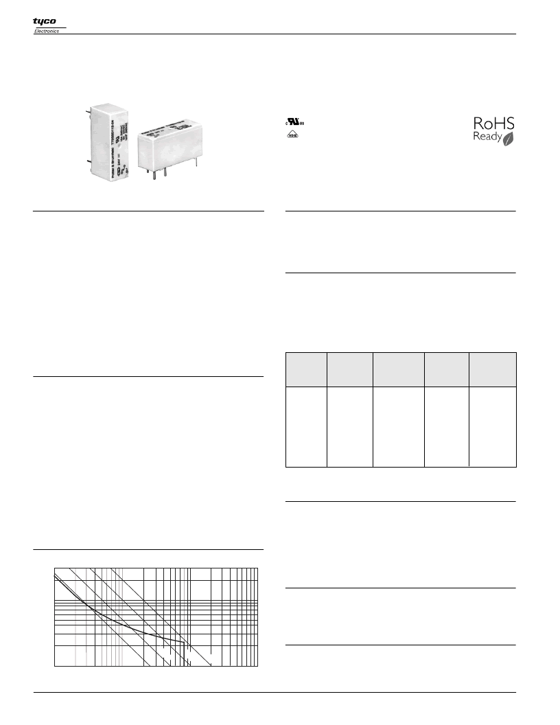
Contact Ratings (See Figure 1):
Maximum Switched Voltage:
380VAC.
Maximum Switched Current:
14/5 (N.O./N.C.) amps, AC resistive;
8 amps DC (see Fig. 1)
Maximum Switched Power:
200W, DC; 2,000VA, AC.
Minimum Required Contact Load:
12V, 100mA.
VDE Contact Ratings:
8 amps, 250VAC.
UL Contact Ratings:
10 amps, 240VAC; 8 amps 24VDC;
1/3 HP, 120VAC; 1/2 HP, 240VAC.
.1
1
10
100
10
100
200W
100W
S200
300
50
40
30
20
25W
Switching Current (Amps DC)
50W
ENVIRONMENTAL DATA
Temperature Range
Storage:
-40
°
C to +130
°
C.
Operating:
-40
°
C to +85
°
C.
DC
Must
Operate
Voltage
Nominal
Coil
Current
(mA)
75.0
42.4
36.4
24.7
18.5
12.4
10.6
6.4
5.5
3.9
Nominal
Voltage
Resistance
in Ohms
±
10%
3
5
6
9
40
118
165
365
650
1,455
2,270
5,460
8,790
15,265
2.1
3.4
4.1
6.1
8.2
12.3
16.3
24.5
32.6
40.8
DC
Coils
12
18
24
36
48
60
Figure 1 - DC Switching Load Limit Curve
Users should thoroughly review the technical data before selecting a product part number. It
is recommended that user also seek out the pertinent approvals files of the agencies/
laboratories and review them to ensure the product meets the requirements for a given
application.
相關(guān)PDF資料 |
PDF描述 |
|---|---|
| 143-131A | COLD JUNCTION COMPENSATION MODULE |
| 143 | Custom Commercial Modules |
| 1442 | Bulk Metal?? Foil Technology Dual-In-Line Hermetic Resistor Networks |
| 1445420-3 | Miniature CPC (Circular Plastic Connector) |
| 1445420-5 | Miniature CPC (Circular Plastic Connector) |
相關(guān)代理商/技術(shù)參數(shù) |
參數(shù)描述 |
|---|---|
| 1423091-6 | 制造商:TE Connectivity 功能描述:T9AV5L12-12=T9A - Bulk 制造商:TE CONNECTIVITY P&B 功能描述:T9AV5L12-12=T9A |
| 1423092-1 | 功能描述:通用繼電器 KUHP-5A51-277=KU REL RoHS:否 制造商:Omron Electronics 觸點形式:1 Form A (SPST-NO) 觸點電流額定值:150 A 線圈電壓:24 VDC 線圈電阻:144 Ohms 線圈電流:167 mA 切換電壓:400 V 安裝風(fēng)格:Chassis 觸點材料: |
| 1423094-1 | 制造商:TE Connectivity 功能描述:Electromechanical Relay SPDT 30A 12VDC 155Ohm Through Hole 制造商:TE Connectivity 功能描述:T90S5D42-12=RELAY - Bulk 制造商:TE Connectivity 功能描述:RELAY GEN PURPOSE SPDT 20A 12V 制造商:TE CONNECTIVITY P&B 功能描述:Electromechanical Relay SPDT 30A 12VDC 155Ohm Through Hole |
| 1423097-7 | 制造商:TE Connectivity 功能描述:T9AV1D24-12 - Bulk |
| 14230LG | 功能描述:助聽器與助視器 45" 60w Wall Gray RoHS:否 制造商:Luxo Corporation 安裝風(fēng)格:Metal Base 長度:30 in 顏色:Light Gray |
發(fā)布緊急采購,3分鐘左右您將得到回復(fù)。