- 您現在的位置:買賣IC網 > PDF目錄366129 > 1N4004G-T (DIODES INC) 1.0A GLASS PASSIVATED RECTIFIER PDF資料下載
參數資料
| 型號: | 1N4004G-T |
| 廠商: | DIODES INC |
| 元件分類: | 參考電壓二極管 |
| 英文描述: | 1.0A GLASS PASSIVATED RECTIFIER |
| 中文描述: | 1 A, 400 V, SILICON, SIGNAL DIODE, DO-41 |
| 封裝: | ROHS COMPLIANT, PLASTIC PACKAGE-2 |
| 文件頁數: | 1/3頁 |
| 文件大小: | 77K |
| 代理商: | 1N4004G-T |
e
3
DS29002 Rev. 6 - 2
1 of 3
1N4001G/L-1N4007G/L
www.diodes.com
Diodes Incorporated
1N4001G/L - 1N4007G/L
1.0A GLASS PASSIVATED RECTIFIER
Features
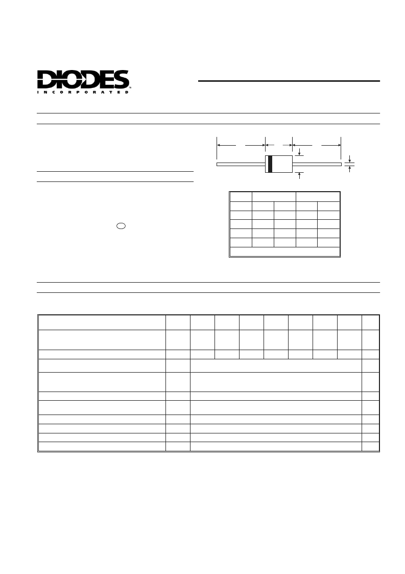
“L” Suffix Designates A-405 Package
No Suffix Designates DO-41 Package
DO-41 Plastic
Min
A-405
Dim
A
B
C
D
Max
Min
Max
25.40
—
25.40
—
4.06
5.21
4.10
5.20
0.71
0.864
0.53
0.64
2.00
2.72
2.00
2.70
All Dimensions in mm
A
A
B
C
D
Maximum Ratings and Electrical Characteristics
@ T
A
= 25°C unless otherwise specified
Glass Passivated Die Construction
High Current Capability and Low Forward Voltage Drop
Surge Overload Rating to 30A Peak
Lead Free Finish, RoHS Compliant (Note 4)
Mechanical Data
Case: DO-41 Plastic, A-405
Case Material: Molded Plastic. UL Flammability
Classification Rating 94V-0
Moisture Sensitivity: Level 1 per J-STD-020C
Terminals: Finish - Tin. Plated Leads Solderable per
MIL-STD-202, Method 208
Polarity: Cathode Band
Ordering Information: See Last Page
Marking: Type Number
Weight: DO-41 0.30 grams (approximate)
A-405 0.20 grams (approximate)
Single phase, half wave, 60Hz, resistive or inductive load.
For capacitive load, derate current by 20%.
Characteristic
Symbol
1N4001
G/GL
1N4002
G/GL
1N4003
G/GL
1N4004
G/GL
1N4005
G/GL
1N4006
G/GL
1N4007
G/GL
Unit
Peak Repetitive Reverse Voltage
Working Peak Reverse Voltage
DC Blocking Voltage
RMS Reverse Voltage
Average Rectified Output Current
(Note 1)
Non-Repetitive Peak Forward Surge Current
8.3ms single half sine-wave superimposed on
rated load
Forward Voltage
Peak Reverse Current
at Rated DC Blocking Voltage
V
RRM
V
RWM
V
R
V
R(RMS)
50
100
200
400
600
800
1000
V
35
70
140
280
420
560
700
V
@ T
A
= 75°C
I
O
1.0
A
I
FSM
30
A
@ I
F
= 1.0A
@T
A
= 25°C
@ T
A
= 125°C
V
FM
1.0
5.0
50
2.0
8.0
100
V
I
RM
μA
Reverse Recovery Time (Note 3)
Typical Total Capacitance (Note 2)
Typical Thermal Resistance Junction to Ambient
Operating and Storage Temperature Range
t
rr
C
T
R
JA
T
j,
T
STG
μs
pF
°C/W
°C
-65 to +175
Notes: 1. Leads maintained at ambient temperature at a distance of 9.5mm from the case.
2. Measured at 1.0 MHz and applied reverse voltage of 4.0V DC.
3. Measured with I
F
= 0.5A, I
R
= -1A, I
rr
= 0.25A.
4. RoHS revision 13.2.2003. Glass and High Temperature Solder Exemptions Applied, see EU Directive Annex Notes 5 and 7.
相關PDF資料 |
PDF描述 |
|---|---|
| 1N4005G-A | 1.0A GLASS PASSIVATED RECTIFIER |
| 1N4005G-B | 1.0A GLASS PASSIVATED RECTIFIER |
| 1N4005GL-T | 1.0A GLASS PASSIVATED RECTIFIER |
| 1N4005G-T | 1.0A GLASS PASSIVATED RECTIFIER |
| 1N4006G-A | 1.0A GLASS PASSIVATED RECTIFIER |
相關代理商/技術參數 |
參數描述 |
|---|---|
| 1N4004G-T3 | 制造商:WTE 制造商全稱:Won-Top Electronics 功能描述:1.0A GLASS PASSIVATED STANDARD DIODE |
| 1N4004G-TB | 制造商:WTE 制造商全稱:Won-Top Electronics 功能描述:1.0A GLASS PASSIVATED STANDARD DIODE |
| 1N4004G-T-S-NT | 功能描述:整流器 GP, Junc Plas Rect 1A,400V RoHS:否 制造商:Vishay Semiconductors 產品:Standard Recovery Rectifiers 配置: 反向電壓:100 V 正向電壓下降: 恢復時間:1.2 us 正向連續電流:2 A 最大浪涌電流:35 A 反向電流 IR:5 uA 安裝風格:SMD/SMT 封裝 / 箱體:DO-221AC 封裝:Reel |
| 1N4004H-T | 制造商:MCC 制造商全稱:Micro Commercial Components 功能描述:1 Amp Rectifier 50 - 1000 Volts |
| 1N4004ID | 制造商:PHILIPS 制造商全稱:NXP Semiconductors 功能描述:Rectifiers |
發布緊急采購,3分鐘左右您將得到回復。