- 您現(xiàn)在的位置:買賣IC網(wǎng) > PDF目錄248525 > 4N28 (QUALITY TECHNOLOGIES CORP) 1 CHANNEL TRANSISTOR OUTPUT OPTOCOUPLER PDF資料下載
參數(shù)資料
| 型號(hào): | 4N28 |
| 廠商: | QUALITY TECHNOLOGIES CORP |
| 元件分類: | Optocoupler - Transistor Output |
| 英文描述: | 1 CHANNEL TRANSISTOR OUTPUT OPTOCOUPLER |
| 封裝: | PLASTIC, DIP-6 |
| 文件頁數(shù): | 1/6頁 |
| 文件大小: | 246K |
| 代理商: | 4N28 |
1
Motorola Optoelectronics Device Data
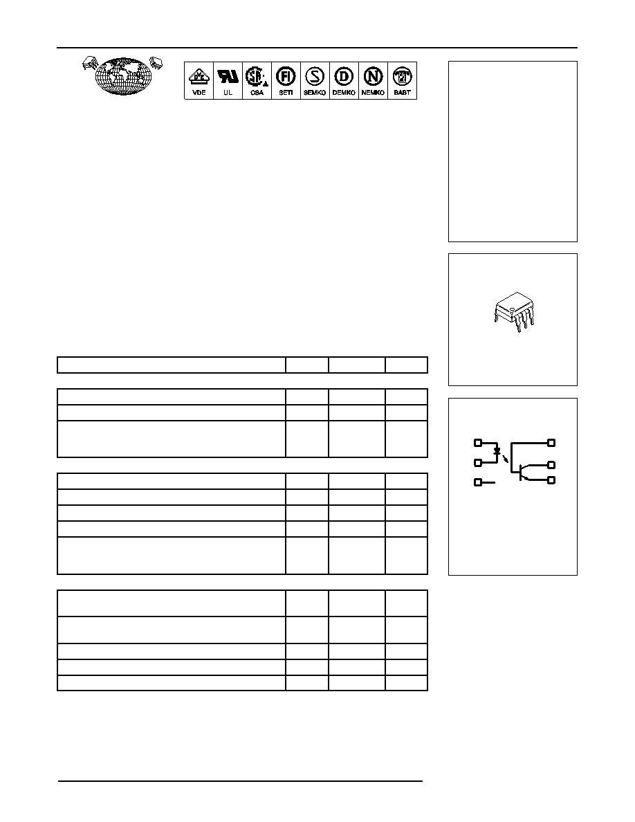
6-Pin DIP Optoisolators
Transistor Output
The 4N25/A, 4N26, 4N27 and 4N28 devices consist of a gallium arsenide
infrared emitting diode optically coupled to a monolithic silicon phototransistor
detector.
Most Economical Optoisolator Choice for Medium Speed, Switching Applications
Meets or Exceeds All JEDEC Registered Specifications
To order devices that are tested and marked per VDE 0884 requirements, the
suffix ”V” must be included at end of part number. VDE 0884 is a test option.
Applications
General Purpose Switching Circuits
Interfacing and coupling systems of different potentials and impedances
I/O Interfacing
Solid State Relays
MAXIMUM RATINGS (TA = 25°C unless otherwise noted)
Rating
Symbol
Value
Unit
INPUT LED
Reverse Voltage
VR
3
Volts
Forward Current — Continuous
IF
60
mA
LED Power Dissipation @ TA = 25°C
with Negligible Power in Output Detector
Derate above 25
°C
PD
120
1.41
mW
mW/
°C
OUTPUT TRANSISTOR
Collector–Emitter Voltage
VCEO
30
Volts
Emitter–Collector Voltage
VECO
7
Volts
Collector–Base Voltage
VCBO
70
Volts
Collector Current — Continuous
IC
150
mA
Detector Power Dissipation @ TA = 25°C
with Negligible Power in Input LED
Derate above 25
°C
PD
150
1.76
mW
mW/
°C
TOTAL DEVICE
Isolation Surge Voltage(1)
(Peak ac Voltage, 60 Hz, 1 sec Duration)
VISO
7500
Vac(pk)
Total Device Power Dissipation @ TA = 25°C
Derate above 25
°C
PD
250
2.94
mW
mW/
°C
Ambient Operating Temperature Range(2)
TA
– 55 to +100
°C
Storage Temperature Range(2)
Tstg
– 55 to +150
°C
Soldering Temperature (10 sec, 1/16
″ from case)
TL
260
°C
1. Isolation surge voltage is an internal device dielectric breakdown rating.
1. For this test, Pins 1 and 2 are common, and Pins 4, 5 and 6 are common.
2. Refer to Quality and Reliability Section in Opto Data Book for information on test conditions.
Preferred devices are Motorola recommended choices for future use and best overall value.
GlobalOptoisolator is a trademark of Motorola, Inc.
Order this document
by 4N25/D
MOTOROLA
SEMICONDUCTOR TECHNICAL DATA
GlobalOptoisolator
4N25
4N25A
4N26
4N27
4N28
*Motorola Preferred Devices
*
SCHEMATIC
PIN 1. LED ANODE
2. LED CATHODE
3. N.C.
4. EMITTER
5. COLLECTOR
6. BASE
1
2
3
6
5
4
[CTR = 20% Min]
*
[CTR = 10% Min]
STANDARD THRU HOLE
CASE 730A–04
STYLE 1 PLASTIC
6
1
4N25
4N25A
4N26
4N27
4N28
Motorola, Inc. 1995
REV 5
QT Optoelectronics
相關(guān)PDF資料 |
PDF描述 |
|---|---|
| 4N33 | 1 CHANNEL DARLINGTON OUTPUT OPTOCOUPLER |
| 4N36 | 1 CHANNEL TRANSISTOR OUTPUT OPTOCOUPLER |
| 4N35 | 1 CHANNEL TRANSISTOR OUTPUT OPTOCOUPLER |
| 4N26 | 1 CHANNEL TRANSISTOR OUTPUT OPTOCOUPLER |
| 4N25 | 1 CHANNEL TRANSISTOR OUTPUT OPTOCOUPLER |
相關(guān)代理商/技術(shù)參數(shù) |
參數(shù)描述 |
|---|---|
| 4N28 HAR91 | 制造商:HAR 功能描述:4N28 |
| 4N28(SHORT) | 制造商:Toshiba America Electronic Components 功能描述:Optocoupler DC-IN 1-CH Transistor With Base DC-OUT 6-Pin PDIP |
| 4N28 | 制造商:Fairchild Semiconductor Corporation 功能描述:OPTOCOUPLER TRANSISTOR O/P 制造商:Vishay Semiconductors 功能描述:Optocoupler |
| 4N28.300 | 制造商:Fairchild Semiconductor Corporation 功能描述:OPTOCOUPLER TRANSISTOR O/P |
| 4N28.300 | 制造商:Fairchild Semiconductor Corporation 功能描述:OPTOCOUPLER TRANSISTOR O/P |
發(fā)布緊急采購,3分鐘左右您將得到回復(fù)。