- 您現在的位置:買賣IC網 > PDF目錄371601 > 50988 KFD2-SRA-EX-4 PDF資料下載
參數資料
| 型號: | 50988 |
| 英文描述: | KFD2-SRA-EX-4 |
| 中文描述: | KFD2 -儲備金帳戶,前4 |
| 文件頁數: | 1/4頁 |
| 文件大小: | 278K |
| 代理商: | 50988 |
1
A
2
Subject to reasonable modifications due to technical advances.
Pepperl+Fuchs Group Tel.: Germany (06 21) 7 76-0 USA (330) 4 25 35 55 Singapore 7 79 90 91 Internet http://www.pepperl-fuchs.com
Copyright Pepperl+Fuchs, Printed in Germany
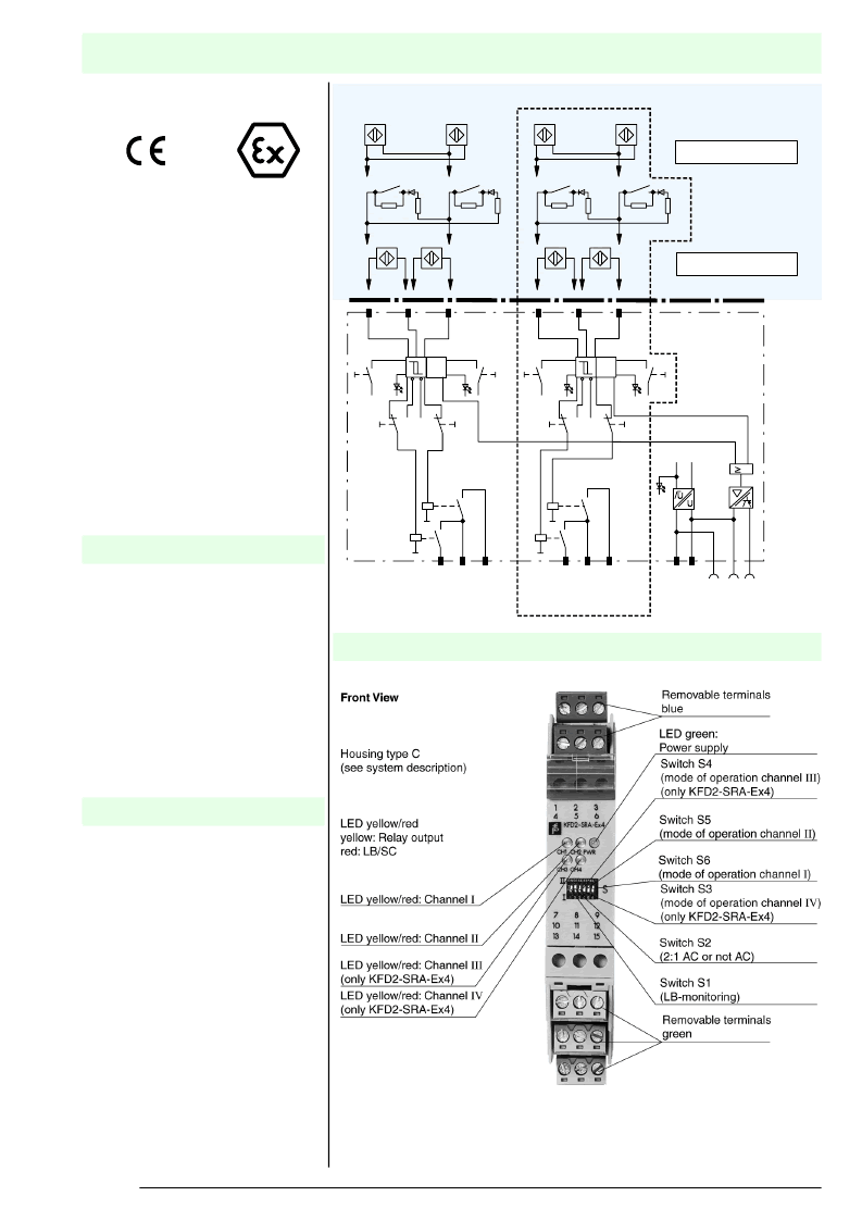
Transformer Isolated Barriers
KFD2-SRA-Ex*
Output: Relay
Input
I
Input EEx ia IIC
red
Output
I
Output
II
Output
III
Power
supply
Output
IV
14+ 15-
Power
rail
LB-collective
error message
Switch S2 in position
I
Switch S2 in position
II
S
H
yellow
red
yellow
Resistor for
LB and SC:
R
1
= 400
≤
R
≤
2 k
R
2
= 10 k
2:1 Mode
only KFD2-SRA-Ex4
LB
SC
LB
SC
Input
II
S6
S5
S1
S2
II
II
I
I
III
IV
7
8
9
10
11
12
1
S4
S3
S1
S2
II
II
I
I
+
-
+
-
1
-
-
+
-
+
3
1
R
2
R
1
R
1
R
2
-
+
+
3
1-
2+
2+
3-
1-
2+
3-
4-
5+
5+
6-
4
-
-
+
-
+
6
4
R
2
R
1
R
1
R
2
-
+
+
6
4-
5+
6-
Aufbau
Control circuit EEx ia IIC
24 V DC nominal supply voltage
Reversible mode of operation
Lead monitoring (short circuit LK and
interruption LB) with LED indicator
(red flashing), switching output and
signal on Power Rail
50 % less wiring 2 : 1
2 relay outputs, 1 NO contact per
channel, grouped into single-pole
pairs
EMC acc. to NAMUR NE 21
4-channel
2-channel
KFD2-SRA-Ex4
KFD2-SRA-Ex2
The transformer isolated barrier trans-
fers digital signals from the hazardous
area. The inputs are designed for the
connection of NAMUR sensors per
DIN EN 60947-5-6 or a mechanical
contact.
The input, output and power supply are
galvanically isolated from each other.
The relay output and the power supply
are galvanically isolated from each
other per DIN EN 50178 with a design
isolation voltage of AC 50 V.
Min/Max manometer, valve positioners,
magnetic immersion probes with 2
switch points.
Two signals can be monitored through
one dual lead in the 2:1 mode of opera-
tion (AC), reducing wiring by fifty per-
cent.
Function
Application
相關PDF資料 |
PDF描述 |
|---|---|
| 50AP016 | Dual/Triple Ultra-Low-Voltage SOT23 µP Supervisory Circuits |
| 50S067 | Dual/Triple Ultra-Low-Voltage SOT23 µP Supervisory Circuits |
| 50B5814 | TRANSISTOR MOSFET TO-220 |
| 50GAL120DN2 | IGBT Module |
| 50GB120DN2 | Dual/Triple Ultra-Low-Voltage SOT23 µP Supervisory Circuits |
相關代理商/技術參數 |
參數描述 |
|---|---|
| 50989 | 制造商:Master Appliance Corp 功能描述:BLOWER WHEEL, METAL |
| 5098AS | 功能描述:烙鐵 PISTOL GRIP DESOLD RoHS:否 制造商:Weller 產品:Soldering Stations 類型:Digital, Iron, Stand, Cleaner 瓦特:50 W 最大溫度:+ 850 F 電纜類型:US Cord Included |
| 5098B1100B1 | 制造商:Schurter Electronic Components 功能描述: |
| 5098C | 制造商:Alpha Wire Company 功能描述:CABLE 24AWG SCRN 8CORE PER M |
| 5098C BK199 | 制造商:Alpha Wire Company 功能描述:5098C BLACK 1000 = 1000 FT |
發布緊急采購,3分鐘左右您將得到回復。