- 您現(xiàn)在的位置:買賣IC網(wǎng) > PDF目錄56756 > 5D5.090RM 2-OUTPUT 1 W DC-DC REG PWR SUPPLY MODULE PDF資料下載
參數(shù)資料
| 型號: | 5D5.090RM |
| 元件分類: | 電源模塊 |
| 英文描述: | 2-OUTPUT 1 W DC-DC REG PWR SUPPLY MODULE |
| 封裝: | DIP-24 |
| 文件頁數(shù): | 2/2頁 |
| 文件大小: | 63K |
| 代理商: | 5D5.090RM |
A
2 Watt RM Dual Series DC/DC Converters
2401 Stanwell Drive Concord, California 94520 Ph: 925/687-4411 or 800/542-3355 Fax: 925/687-3333 www.calex.com Email: sales@calex.com
2
3/2001
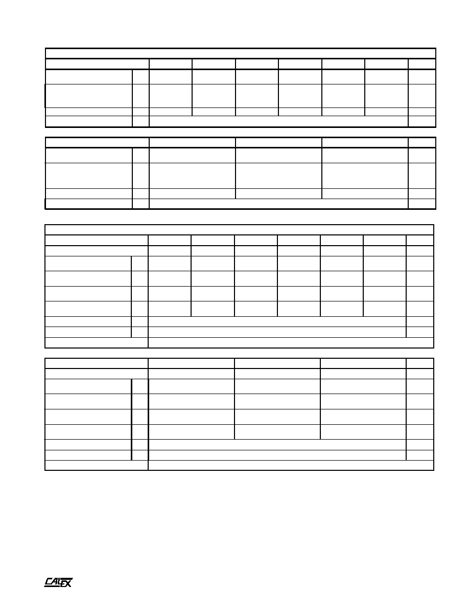
Notes:
*
All parameters measured at Tc = 25°C, nominal input voltage,
and full rated load, unless
otherwise
noted.
Refer to
CALEX Application Notes for definition of terms,
measurement circuits, and other information.
(1)
The case thermal impedance is specified as the case temperature
rise over ambient per internal watt dissipated.
All tests with connections to all active pins. Operation with
connection to only one pin will not harm the unit.
*
s
r
e
t
e
m
a
r
a
P
t
u
p
n
I
l
e
d
o
MM
R
0
9
0
.
5
D
5M
R
5
8
0
.
2
1
D
5M
R
0
7
0
.
5
1
D
5M
R
0
9
0
.
5
D
2
1M
R
5
8
0
.
2
1
D
2
1M
R
0
7
0
.
5
1
D
2
1s
t
i
n
U
e
g
n
a
R
e
g
a
t
l
o
V
N
I
M
X
A
M
5
.
4
5
.
5
.
4
5
.
5
.
4
5
.
5
8
.
0
1
2
.
3
1
8
.
0
1
2
.
3
1
8
.
0
1
2
.
3
1
C
D
V
t
n
e
r
u
C
t
u
p
n
I
d
a
o
L
ll
u
F
d
a
o
L
o
N
P
Y
T
P
Y
T
5
7
3
0
4
6
1
7
3
5
0
1
7
0
6
0
7
1
0
5
9
2
0
5
0
3
0
5
A
m
y
c
n
e
i
c
i
f
EP
Y
T8
47
59
54
47
59
5%
y
c
n
e
u
q
e
r
F
g
n
i
h
c
t
i
w
SP
Y
T0
2
2z
H
k
l
e
d
o
MM
R
0
9
0
.
5
D
4
2M
R
5
8
0
.
2
1
D
4
2M
R
0
7
0
.
5
1
D
4
2s
t
i
n
U
e
g
n
a
R
e
g
a
t
l
o
V
N
I
M
X
A
M
6
.
1
2
4
.
6
2
6
.
1
2
4
.
6
2
6
.
1
2
4
.
6
2
C
D
V
t
n
e
r
u
C
t
u
p
n
I
d
a
o
L
ll
u
F
d
a
o
L
o
N
P
Y
T
P
Y
T
7
8
0
2
5
1
0
2
3
5
1
0
2
A
m
y
c
n
e
i
c
i
f
EP
Y
T3
45
57
5%
y
c
n
e
u
q
e
r
F
g
n
i
h
c
t
i
w
SP
Y
T0
2
2z
H
k
*
s
r
e
t
e
m
a
r
a
P
t
u
p
t
u
O
l
e
d
o
MM
R
0
9
0
.
5
D
5M
R
5
8
0
.
2
1
D
5M
R
0
7
0
.
5
1
D
5M
R
0
9
0
.
5
D
2
1M
R
5
8
0
.
2
1
D
2
1M
R
0
7
0
.
5
1
D
2
1s
t
i
n
U
e
g
a
t
l
o
V
t
u
p
t
u
O5
±2
1
±5
1
±5
±2
1
±5
1
±C
D
V
y
c
a
r
u
c
A
e
g
a
t
l
o
V
t
u
p
t
u
O
N
I
M
X
A
M
0
8
.
4
0
2
.
5
4
6
.
1
6
3
.
2
1
5
.
4
1
5
4
.
5
1
0
8
.
4
0
2
.
5
4
6
.
1
6
3
.
2
1
5
.
4
1
5
4
.
5
1
C
D
V
e
g
n
a
R
d
a
o
L
d
e
t
a
R
N
I
M
X
A
M
0
9
±
0
5
8
±
0
7
±
0
9
±
0
5
8
±
0
7
±
A
m
n
o
i
t
a
l
u
g
e
R
d
a
o
L
d
a
o
L
x
a
M
-
n
i
M
P
Y
T
X
A
M
4
.
0
2
5
.
0
1
5
.
0
1
4
.
0
2
5
.
0
1
5
.
0
1
%
n
o
i
t
a
l
u
g
e
R
e
n
i
L
e
n
i
L
x
a
M
-
n
i
M
P
Y
T
X
A
M
1
.
0
1
5
.
0
1
5
.
0
1
.
0
1
5
.
0
1
5
.
0
1
%
)
2
(
k
a
e
P
-
k
a
e
P
,
e
s
i
o
NP
Y
T0
5P
-
P
V
m
t
n
e
i
c
i
f
e
o
C
e
r
u
t
a
r
e
p
m
e
TP
Y
T0
0
2C
°
/
m
p
t
i
u
c
r
i
C
t
r
o
h
S
y
r
e
v
o
c
e
R
o
t
u
A
,
s
u
o
u
n
i
t
n
o
C
l
e
d
o
MM
R
0
9
0
.
5
D
4
2M
R
5
8
0
.
2
1
D
4
2M
R
0
7
0
.
5
1
D
4
2s
t
i
n
U
e
g
a
t
l
o
V
t
u
p
t
u
O5
±2
1
±5
1
±C
D
V
y
c
a
r
u
c
A
e
g
a
t
l
o
V
t
u
p
t
u
O
N
I
M
X
A
M
0
8
.
4
0
2
.
5
4
6
.
1
6
3
.
2
1
5
.
4
1
5
4
.
5
1
C
D
V
e
g
n
a
R
d
a
o
L
d
e
t
a
R
N
I
M
X
A
M
0
9
±
0
5
8
±
0
7
±
A
m
n
o
i
t
a
l
u
g
e
R
d
a
o
L
d
a
o
L
x
a
M
-
n
i
M
P
Y
T
X
A
M
4
.
0
2
5
.
0
1
5
.
0
1
%
n
o
i
t
a
l
u
g
e
R
e
n
i
L
e
n
i
L
x
a
M
-
n
i
M
P
Y
T
X
A
M
1
.
0
1
5
.
0
1
5
.
0
1
%
)
2
(
k
a
e
P
-
k
a
e
P
,
e
s
i
o
NP
Y
T0
5P
-
P
V
m
t
n
e
i
c
i
f
e
o
C
e
r
u
t
a
r
e
p
m
e
TP
Y
T0
0
2C
°
/
m
p
t
i
u
c
r
i
C
t
r
o
h
S
y
r
e
v
o
c
e
R
o
t
u
A
,
s
u
o
u
n
i
t
n
o
C
(2)
Noise is measured per CALEX Application Notes. Measurement
bandwidth is 0 - 20 MHz. Noise measurements are made with
0.1F ceramic capacitor connected between output and CMN
pins.
(3)
Specifications subject to change without notice.
相關(guān)PDF資料 |
PDF描述 |
|---|---|
| 12D5.090RM | 2-OUTPUT 1 W DC-DC REG PWR SUPPLY MODULE |
| 12D15.070RM | 2-OUTPUT 2 W DC-DC REG PWR SUPPLY MODULE |
| 5D15.070RM | 2-OUTPUT 2 W DC-DC REG PWR SUPPLY MODULE |
| 5D12.085RM | 2-OUTPUT 2 W DC-DC REG PWR SUPPLY MODULE |
| 5D5.100SMT | 2-OUTPUT 1 W DC-DC REG PWR SUPPLY MODULE |
相關(guān)代理商/技術(shù)參數(shù) |
參數(shù)描述 |
|---|---|
| 5D50EAG1W00793 | 功能描述:IO NICU CF V0 制造商:laird technologies emi 系列:* 零件狀態(tài):過期 標(biāo)準(zhǔn)包裝:12 |
| 5D-51-90 | 制造商:EMERSON SENSING 功能描述:FAN/LIGHT |
| 5-D-6-1-AC | 制造商:Eaton Corporation 功能描述:COUNTER |
| 5D61CL | 制造商:Eaton Corporation 功能描述:COUNTER |
| 5D71KAG1W01725 | 制造商:Laird Technologies Inc 功能描述:GK,NICU,CF,KC,V0 / .080X.150X17.250IN / UOM=EA |
發(fā)布緊急采購,3分鐘左右您將得到回復(fù)。