- 您現在的位置:買賣IC網 > PDF目錄24576 > 9-1440002-3 POWER/SIGNAL RELAY, 4PDT, MOMENTARY, 1400mW (COIL), 3A (CONTACT), 24VDC (CONTACT), PANEL MOUNT PDF資料下載
參數資料
| 型號: | 9-1440002-3 |
| 元件分類: | 功率/信號繼電器 |
| 英文描述: | POWER/SIGNAL RELAY, 4PDT, MOMENTARY, 1400mW (COIL), 3A (CONTACT), 24VDC (CONTACT), PANEL MOUNT |
| 封裝: | ROHS COMPLIANT |
| 文件頁數: | 1/4頁 |
| 文件大小: | 1471K |
| 代理商: | 9-1440002-3 |
09-2010, Rev. 0910
2010 Tyco Electronics Ltd.
Datasheets and product specification ac-
cording to IEC 61810-1 and to be used only
together with the ‘Definitions’ section.
Datasheets and product data is subject to the
terms of the disclaimer and all chapters of
the ‘Definitions’ section, available at
Datasheets, product data, ‘Definitions’ sec-
tion, application notes and all specifications
are subject to change.
1
OEG
General Purpose Relays
Industrial Relays
Miniature Relay PCL
Coil Data
Coil voltage range
6 to 110VDC
6 to 240VAC (50/60Hz)
Max. coil power
110% of rated power
Max. coil temperature
AC coil
115°C
DC coil
105°C
Coil insulation system according UL
class F
Coil versions, DC coil
Coil
Rated
Operate
Release
Coil
Rated coil
code
voltage
resistance
power
VDC
±10 %
mW
01D
6
4.8
0.6
40
900
02D
12
9.6
1.2
160
900
03D
24
19.2
2.4
650
900
04D
48
38.4
4.8
2600
900
05D
100/110
88.0
10.0
11000
1100
All figures are given for coil without pre-energization, at ambient temperature +23°C
Coil versions, AC coil
Coil
Rated
Operate
Release
Coil
Rated coil
code
voltage
resistance
power
VAC
±10%
VA
01A
6
4.8
1.8
10
1.4
02A
12
9.6
3.6
40
1.4
03A
24
19.2
7.2
160
1.4
04A
48
38.4
14.4
600
1.4
05A
100
80.0
30.0
2800
1.4
06A
110/120
96.0
33.0
3400
1.4
07A
200
160.0
60.0
11000
1.4
08A
220/240
192.0
66.0
13600
1.4
All figures are given for coil without pre-energization, at ambient temperature +23°C, 50 Hz
n
Small size, 3A, 5A switching capacity
n
Meets UL and CSA requirements
n
2 pole and 4 pole contact arrangements
n
AC and DC coils with UL Class F (155°C) coil insulation system
standard
n
Optional flange mount case
n
Plug-in terminals or PCB terminals
Typical applications
Factory automation, process controls, electrical panels, etc.
Approvals
cUL E58304, TUV R50138495, CSA 1017162(LR48471-207),
CQC CQC08001025963
Technical data of approved types on request
Contact Data
2 pole
4 pole
Contact arrangement
2 form A (2NO)
4 form A (4NO)
2 form C (2CO)
4 form C (4CO)
Rated voltage
250VAC, 24VDC
Rated current
5A
3A
Switching power
1100VA, 120W
660VA, 72W
Contact material
Ag, AgSnO2, AgCdO
Min. recommended contact load
100mA at 5VDC
Initial contact resistance
50m at 6VDC, 1A
Frequency of operation
with/without load
30/300min-1
Operate/release time max.
AC coil
20/20ms
DC coil
15/8ms
Electrical endurance
100x103 ops. at rated load
Contact ratings
5A at 250VAC/24VDC resistive
3A at 250VAC/24VDC resistive
Mechanical endurance
100x106 ops.
713
Dimensions are shown for
reference purposes only.
Dimensions are in inches over
(millimeters) unless otherwise
specified.
Specifications and availability
subject to change.
www.tycoelectronics.com
Technical support:
Refer to inside back cover.
OEG
Catalog 1308242
Issued 3-03 (PDF Rev. 3-04)
Features
Small size, 3A, 5A, 10A and 15A switching capacity.
Meets UL and CSA requirements.
1 pole, 2 poles and 4 poles contact arrangements.
AC and DC coils with UL Class F (155
°C) coil insulation system standard.
Optional flange mount case.
Plug-in terminals or PCB terminals.
Contact Data @ 20
°C
Arrangements: 1 Form A (SPST-NO),
1 Form C (SPDT),
2 Form A (DPST-NO),
2 Form C (DPDT),
4 Form A (4PST-NO),
4 Form C (4PDT).
Material: Ag, Ag Alloy.
Max.Switching Rate: 300ops./min.(Mechanical).
30ops./min.(Electrical).
Expected Mechanical Life: 100 million operations (no load).
Expected Electrical Life: 100,000 operations (rated load).
Minimum Load: 100mA @ 5VDC.
Initial Contact Resistance: 50milliohms @ DC6V,1A.
Contact Ratings
Ratings:
PCL-4
3A @ AC250V/DC24V resistive.
PCL-2
5A @ AC250V/DC24V resistive.
PCLH-2 15A @ AC120V resistive.
10A @ AC250V/DC24V resistive.
PCLH-1 15A @ AC250V/DC24V resistive.
Max. Switched Current: PCL-4
3A.
PCL-2
5A.
PCLH-2
15A.
PCLH-1
15A.
Max. Switched Power:
PCL-4
660VA, 72W.
PCL-2
1,100VA, 120W.
PCLH-2
3,168VA, 240W.
PCLH-1
3,300VA, 360W.
Initial Dielectric Strength
Between Open Contacts: 1,000VAC 1minute.
Between Adjacent Contact Terminals: 1,500VAC 1minute.
Between Contacts and Coil: 2,000VAC 1minute.
Surge Voltage (Coil-Contact): 3,000V(1.2/50
s).
Initial Insulation Resistance
Between Open Contacts: 1,000Mohms @ 500VDC.
Between Adjacent Contact Terminals: 1,000Mohms @ 500VDC.
Between Contacts and Coil: 1,000Mohms @ 500VDC.
Coil Data
Voltage: AC 6 - 240V.
DC 6 - 110V.
Nominal Power: AC abt. 1.4VA/1.2VA (50Hz/60Hz).
DC abt. 0.9W.
Coil Temperature Rise: AC 60
°C max.
DC 50
°C max.
Max. Coil Power: 110% of nominal voltage.
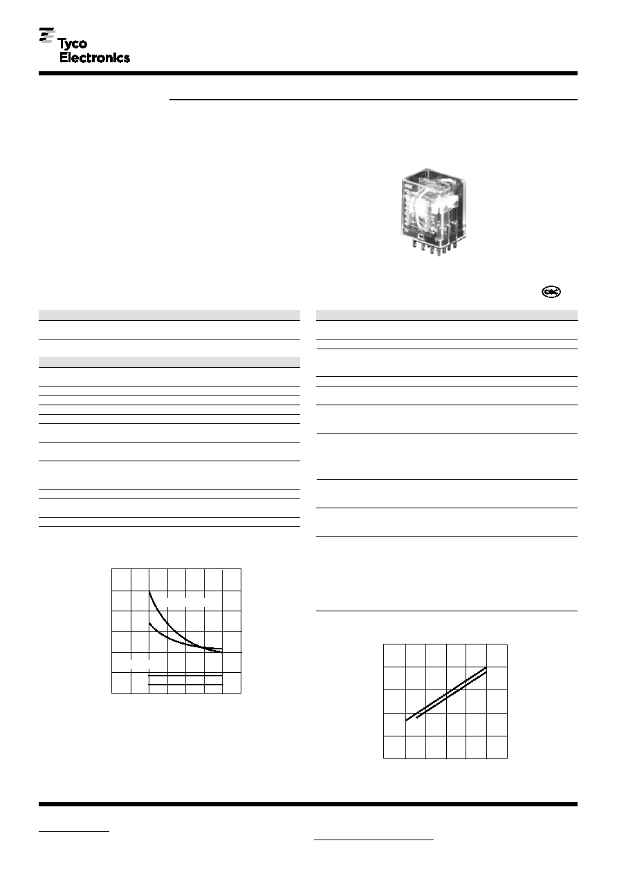
PCL/PCLH series
3A, 5A, 10A, 15A General Purpose
Miniature Relay
Factory Automation, Process Controls,
Electrical Panels, etc.
UL File No. E58304
CSA File No. LR48471
Coil Data@ 20
°C
Operate Data @ 20
°C
Must Operate Voltage: AC 80% of nominal voltage or less.
DC 80% of nominal voltage or less.
Must Release Voltage: AC 30% of nominal voltage or more.
DC 10% of nominal voltage or more.
Operate Time: AC 20ms max.
DC 15ms max.
Release Time: AC 20ms max.
DC 8ms max.
Environmental Data
Temperature Range:
Operating: -10
°C to +55°C.
Humidity: 45 to 85%. (Non-condensing).
Vibration, Operational: 10 to 55Hz 1.0mm double amplitude.
Mechanical: 10 to 55Hz 1.0mm double amplitude.
Shock, Operational: 100m/s2 (abt. 10G).
Mechanical: 1,000m/s2 (abt. 100G).
Mechanical Data
Termination: Plug-in, PCB.
Enclosure: Snap-on cover.
Weight: 1.26 oz (32g) approximately.
PCL AC Coil
6
10
12
40
24
160
48
600
80% max.
30% min.
abt. 1.4
100
2,800
110/120
3,400
200
11,000
220/240
13,600
Coil
Resistance
(ohms)
±10%
Nominal Coil
Power
(VA)
Rated Coil
Voltage
(VAC)
PCL DC Coil
Coil
Resistance
(ohms)
±10%
Must Operate
Voltage
(VDC)
Must Release
Voltage
(VDC)
Nominal Coil
Power
(W)
Rated Coil
Voltage
(VDC)
6
40
12
160
24
650
80% max.
10% min.
48
2,600
100/110
11,000
abt. 1.1
Must Operate
Voltage
(VAC)
Must Release
Voltage
(VAC)
abt. 0.9
Users should thoroughly review the technical data before selecting a product part
number. It is recommended that user also seek out the pertinent approvals files of
the agencies/laboratories and review them to ensure the product meets the
requirements for a given application.
716
Dimensions are shown for
reference purposes only.
Dimensions are in inches over
(millimeters) unless otherwise
specified.
Specifications and availability
subject to change.
OEG
Catalog 1308242
Issued 3-03 (PDF Rev. 3-04)
www.tycoelectronics.com
Technical support:
Refer to inside back cover.
Coil Temperature Rise
Operate Time
70
Coil Voltage (% of Rated Nominal)
DC
80
90
100 110 120 130
30
35
20
15
10
5
Time
(msec)
Operate Time
35
Release Time
DC
AC
100
80
60
40
20
0.8
1.2
1.6
2.0
2.4
Temp.
Rise
(°
C)
Coil Power (W,VA)
AC
0.4
Wiring Diagrams (Bottom Views)
PCL 4c type
PCL 2c type
PCL 4a type
PCL 2a type
PCLH 2c type
PCLH 1c type
PCLH 2a type
PCLH 1a type
PC Board Layouts (Bottom Views)
PCL 4pole type
PCLH type
27
.5
1.08
(27.5)
.83
(21.2)
.520
(13.2)
.248
(6.3)
.252
(6.4)
.500
(12.7)
.661
(16.8)
.173
(4.4)
14 – .059 DIA
(1.5)
1.08
(27.5)
.520
(13.2)
.83
(21.2)
.248
(6.3)
.252
(6.4)
.500
(12.7)
.661
(16.8)
8 – .079 DIA
(2.0)
.571
(14.5)
.83
(21.2)
.173
(4.4)
.236
(6.0)
.287
(7.3)
.520
(13.2)
.705
(17.9)
8 – .098 DIA
(2.5)
Reference Data
Sockets
For PCL socket information refer to KH series sockets (page 712).
For PCLH socket information refer to K10 series sockets (page 722).
716
Dimensions are shown for
reference purposes only.
Dimensions are in inches over
(millimeters) unless otherwise
Specifications and availability
subject to change.
OEG
Catalog 1308242
Issued 3-03 (PDF Rev. 3-04)
www.tycoelectronics.com
Technical support:
Refer to inside back cover.
Coil Temperature Rise
Operate Time
70
Coil Voltage (% of Rated Nominal)
DC
80
90
100 110 120 130
30
35
20
15
10
5
Time
(msec)
Operate Time
35
Release Time
DC
AC
100
80
60
40
20
0.8
1.2
1.6
2.0
2.4
Temp.
Rise
(°
C)
Coil Power (W,VA)
AC
0.4
Wiring Diagrams (Bottom Views)
PCL 4c type
PCL 2c type
PCL 4a type
PCL 2a type
PCLH 2c type
PCLH 1c type
PCLH 2a type
PCLH 1a type
PC Board Layouts (Bottom Views)
PCL 4pole type
PCLH type
27
.5
1.08
(27.5)
.83
(21.2)
.520
(13.2)
.248
(6.3)
.252
(6.4)
.500
(12.7)
.661
(16.8)
.173
(4.4)
14 – .059 DIA
(1.5)
1.08
(27.5)
.520
(13.2)
.83
(21.2)
.248
(6.3)
.252
(6.4)
.500
(12.7)
.661
(16.8)
8 – .079 DIA
(2.0)
.571
(14.5)
.83
(21.2)
.173
(4.4)
.236
(6.0)
.287
(7.3)
.520
(13.2)
.705
(17.9)
8 – .098 DIA
(2.5)
Reference Data
Sockets
For PCL socket information refer to KH series sockets (page 712).
For PCLH socket information refer to K10 series sockets (page 722).
t
C
u
相關PDF資料 |
PDF描述 |
|---|---|
| 051-153-0000 | RF Coaxial Connectors |
| 9-1440003-2 | POWER/SIGNAL RELAY, SPDT, MOMENTARY, 0.044A (COIL), 9VDC (COIL), 400mW (COIL), 5A (CONTACT), 277VDC (CONTACT), THROUGH HOLE-STRAIGHT MOUNT |
| 9-1440003-8 | POWER/SIGNAL RELAY, SPDT, MOMENTARY, 0.067A (COIL), 6VDC (COIL), 400mW (COIL), 5A (CONTACT), 277VDC (CONTACT), THROUGH HOLE-STRAIGHT MOUNT |
| 9-1440003-0 | POWER/SIGNAL RELAY, SPDT, MOMENTARY, 0.079A (COIL), 5VDC (COIL), 400mW (COIL), 5A (CONTACT), 30VDC (CONTACT), THROUGH HOLE-STRAIGHT MOUNT |
| 9-1440003-2 | POWER/SIGNAL RELAY, SPDT, MOMENTARY, 0.045A (COIL), 9VDC (COIL), 400mW (COIL), 5A (CONTACT), 30VDC (CONTACT), THROUGH HOLE-STRAIGHT MOUNT |
相關代理商/技術參數 |
參數描述 |
|---|---|
| 9-1440002-5 | 功能描述:通用繼電器 SDT-S-105DMR 003 RoHS:否 制造商:Omron Electronics 觸點形式:1 Form A (SPST-NO) 觸點電流額定值:150 A 線圈電壓:24 VDC 線圈電阻:144 Ohms 線圈電流:167 mA 切換電壓:400 V 安裝風格:Chassis 觸點材料: |
| 9-1440002-6 | 功能描述:通用繼電器 SDT-S-105DMR2 000 RoHS:否 制造商:Omron Electronics 觸點形式:1 Form A (SPST-NO) 觸點電流額定值:150 A 線圈電壓:24 VDC 線圈電阻:144 Ohms 線圈電流:167 mA 切換電壓:400 V 安裝風格:Chassis 觸點材料: |
| 9-1440002-7 | 功能描述:通用繼電器 SDT-S-106LMR2 200 RoHS:否 制造商:Omron Electronics 觸點形式:1 Form A (SPST-NO) 觸點電流額定值:150 A 線圈電壓:24 VDC 線圈電阻:144 Ohms 線圈電流:167 mA 切換電壓:400 V 安裝風格:Chassis 觸點材料: |
| 9-1440002-8 | 功能描述:通用繼電器 SDT-S-109DMR2 000 RoHS:否 制造商:Omron Electronics 觸點形式:1 Form A (SPST-NO) 觸點電流額定值:150 A 線圈電壓:24 VDC 線圈電阻:144 Ohms 線圈電流:167 mA 切換電壓:400 V 安裝風格:Chassis 觸點材料: |
| 9-1440002-9 | 功能描述:通用繼電器 SDT-S-112DMR2 003 RoHS:否 制造商:Omron Electronics 觸點形式:1 Form A (SPST-NO) 觸點電流額定值:150 A 線圈電壓:24 VDC 線圈電阻:144 Ohms 線圈電流:167 mA 切換電壓:400 V 安裝風格:Chassis 觸點材料: |
發布緊急采購,3分鐘左右您將得到回復。