- 您現在的位置:買賣IC網 > PDF目錄36324 > 933656110623 (NXP SEMICONDUCTORS) SQUARE, TIMER, PDSO8 PDF資料下載
參數資料
| 型號: | 933656110623 |
| 廠商: | NXP SEMICONDUCTORS |
| 元件分類: | 模擬波形發生器 |
| 英文描述: | SQUARE, TIMER, PDSO8 |
| 封裝: | 3.90 MM, PLASTIC, SOT-96, SO-8 |
| 文件頁數: | 10/15頁 |
| 文件大?。?/td> | 188K |
| 代理商: | 933656110623 |
Philips Semiconductors
Product data
NE/SA/SE555/SE555C
Timer
2003 Feb 14
4
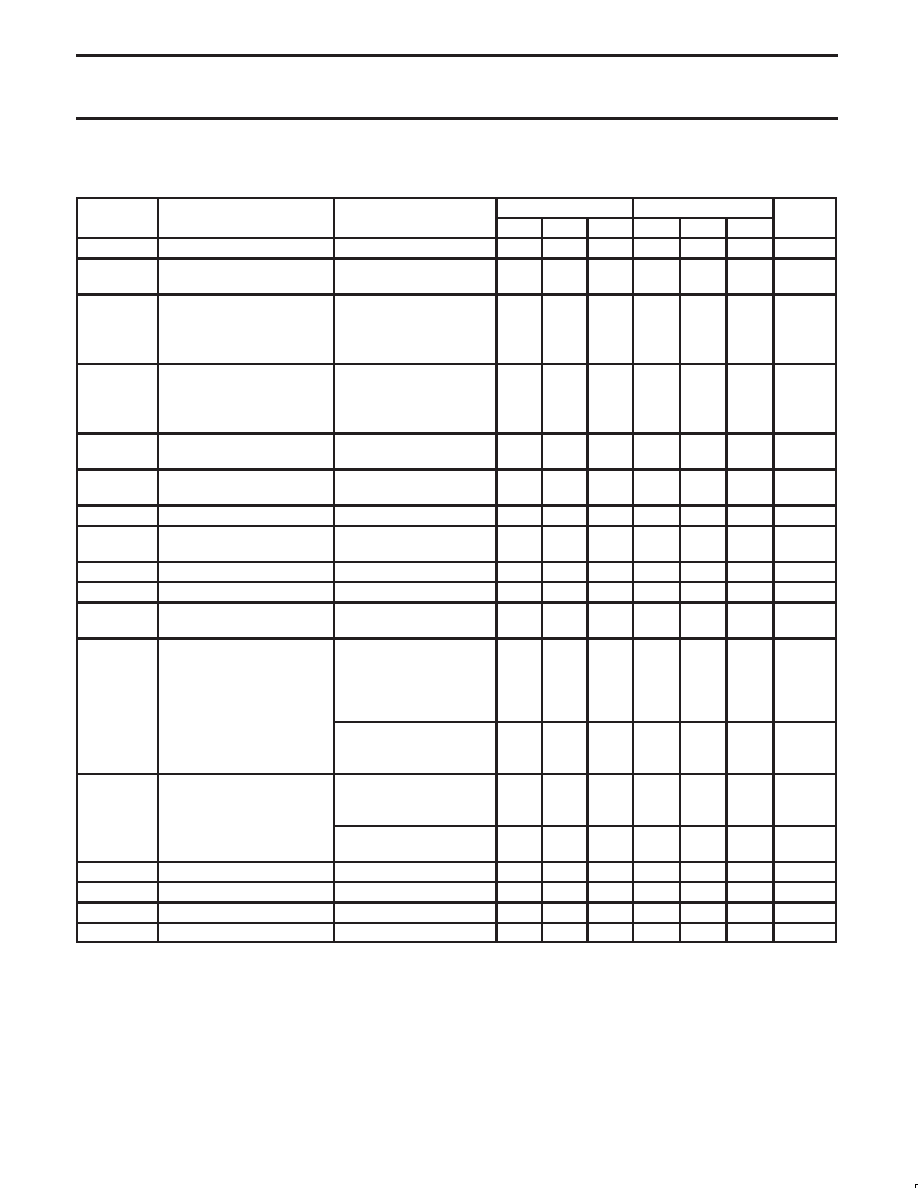
DC AND AC ELECTRICAL CHARACTERISTICS
Tamb = 25 °C, VCC = +5 V to +15 V unless otherwise specified.
SYMBOL
PARAMETER
TEST CONDITIONS
SE555
NE555/SA555/SE555C
UNIT
SYMBOL
PARAMETER
TEST CONDITIONS
Min
Typ
Max
Min
Typ
Max
UNIT
VCC
Supply voltage
4.5
18
4.5
16
V
ICC
Supply current (low state)1
VCC = 5 V, RL = ∞
3
5
3
6
mA
ICC
Su
ly current (low state)
VCC = 15 V, RL = ∞
10
12
10
15
mA
Timing error (monostable)
RA = 2 k to 100 k
tM
Initial accuracy2
C=0.1
F
0.5
2.0
1.0
3.0
%
tM/T
Drift with temperature
30
100
50
150
ppm/
°C
tM/VS
Drift with supply voltage
0.05
0.2
0.1
0.5
%/V
Timing error (astable)
RA, RB = 1 k to 100 k
tA
Initial accuracy2
C = 0.1
F
4
6
5
13
%
tA/T
Drift with temperature
VCC = 15 V
500
ppm/
°C
tA/VS
Drift with supply voltage
0.15
0.6
0.3
1
%/V
VC
Control voltage level
VCC = 15 V
9.6
10.0
10.4
9.0
10.0
11.0
V
VC
Control voltage level
VCC = 5 V
2.9
3.33
3.8
2.6
3.33
4.0
V
VTH
Threshold voltage
VCC = 15 V
9.4
10.0
10.6
8.8
10.0
11.2
V
VTH
Threshold voltage
VCC = 5 V
2.7
3.33
4.0
2.4
3.33
4.2
V
ITH
Threshold current3
0.1
0.25
0.1
0.25
A
VTRIG
Trigger voltage
VCC = 15 V
4.8
5.0
5.2
4.5
5.0
5.6
V
VTRIG
Trigger voltage
VCC = 5 V
1.45
1.67
1.9
1.1
1.67
2.2
V
ITRIG
Trigger current
VTRIG = 0 V
0.5
0.9
0.5
2.0
A
VRESET
Reset voltage4
VCC = 15 V, VTH = 10.5 V
0.3
1.0
0.3
1.0
V
IRESET
Reset current
VRESET = 0.4 V
0.1
0.4
0.1
0.4
mA
IRESET
Reset current
VRESET = 0 V
0.4
1.0
0.4
1.5
mA
VCC = 15 V
ISINK = 10 mA
0.1
0.15
0.1
0.25
V
ISINK = 50 mA
0.4
0.5
0.4
0.75
V
VO
LOW level output voltage
ISINK = 100 mA
2.0
2.2
2.0
2.5
V
VOL
LOW-level output voltage
ISINK = 200 mA
2.5
V
VCC = 5 V
ISINK = 8 mA
0.1
0.25
0.3
0.4
V
ISINK = 5 mA
0.05
0.2
0.25
0.35
V
VCC = 15 V
ISOURCE = 200 mA
12.5
V
VOH
HIGH-level output voltage
ISOURCE = 100 mA
13.0
13.3
12.75
13.3
V
OH
g
VCC = 5 V
ISOURCE = 100 mA
3.0
3.3
2.75
3.3
V
tOFF
Turn-off time5
VRESET = VCC
0.5
2.0
0.5
2.0
s
tR
Rise time of output
100
200
100
300
ns
tF
Fall time of output
100
200
100
300
ns
Discharge leakage current
20
100
20
100
nA
NOTES:
1. Supply current when output high typically 1 mA less.
2. Tested at VCC = 5 V and VCC = 15 V.
3. This will determine the max value of RA+RB, for 15 V operation, the max total R = 10 M, and for 5 V operation, the max. total R = 3.4 M.
4. Specified with trigger input HIGH.
5. Time measured from a positive-going input pulse from 0 to 0.8
×VCC into the threshold to the drop from HIGH to LOW of the output. Trigger is
tied to threshold.
相關PDF資料 |
PDF描述 |
|---|---|
| 933267750602 | SQUARE, TIMER, PDIP8 |
| 933656110602 | SQUARE, TIMER, PDSO8 |
| 933880680112 | INFRARED, TRANSMITTER IC, PDIP28 |
| 933880690112 | INFRARED, TRANSMITTER IC, PDSO28 |
| 933880690118 | INFRARED, TRANSMITTER IC, PDSO28 |
相關代理商/技術參數 |
參數描述 |
|---|---|
| 93365A130 | 制造商:CUSTOMER'S PART # 功能描述: |
| 933663040135 | 制造商:NXP Semiconductors 功能描述:TRANSISTOR PNP 45V 1A SOT89 |
| 933669040652 | 制造商:NXP Semiconductors 功能描述:Inverter Schmitt Trigger 6-Element CMOS 14-Pin PDIP Bulk |
| 9336CMG | 制造商:Apex Tool Group 功能描述:6 IN. DIAGONAL CUTTING S J PLIERS W/CO-MOLDED GRIPS, LASER HARDENED EDGES, CDD |
| 9336CVN | 制造商:Apex Tool Group 功能描述:6 IN. DIAGONAL CUTTING SOLID JOINT PLIERS, CUSHION GRIP, CARDED |
發布緊急采購,3分鐘左右您將得到回復。