- 您現在的位置:買賣IC網 > PDF目錄36331 > 935165940112 (NXP SEMICONDUCTORS) ON-SCREEN DISPLAY IC, PDSO24 PDF資料下載
參數資料
| 型號: | 935165940112 |
| 廠商: | NXP SEMICONDUCTORS |
| 元件分類: | 畫面疊加 |
| 英文描述: | ON-SCREEN DISPLAY IC, PDSO24 |
| 封裝: | PLASTIC, SOT-137-1, SO-24 |
| 文件頁數: | 41/66頁 |
| 文件大小: | 445K |
| 代理商: | 935165940112 |
第1頁第2頁第3頁第4頁第5頁第6頁第7頁第8頁第9頁第10頁第11頁第12頁第13頁第14頁第15頁第16頁第17頁第18頁第19頁第20頁第21頁第22頁第23頁第24頁第25頁第26頁第27頁第28頁第29頁第30頁第31頁第32頁第33頁第34頁第35頁第36頁第37頁第38頁第39頁第40頁當前第41頁第42頁第43頁第44頁第45頁第46頁第47頁第48頁第49頁第50頁第51頁第52頁第53頁第54頁第55頁第56頁第57頁第58頁第59頁第60頁第61頁第62頁第63頁第64頁第65頁第66頁
1995 Jan 19
46
Philips Semiconductors
Preliminary specication
Stand-alone OSD
PCA8515
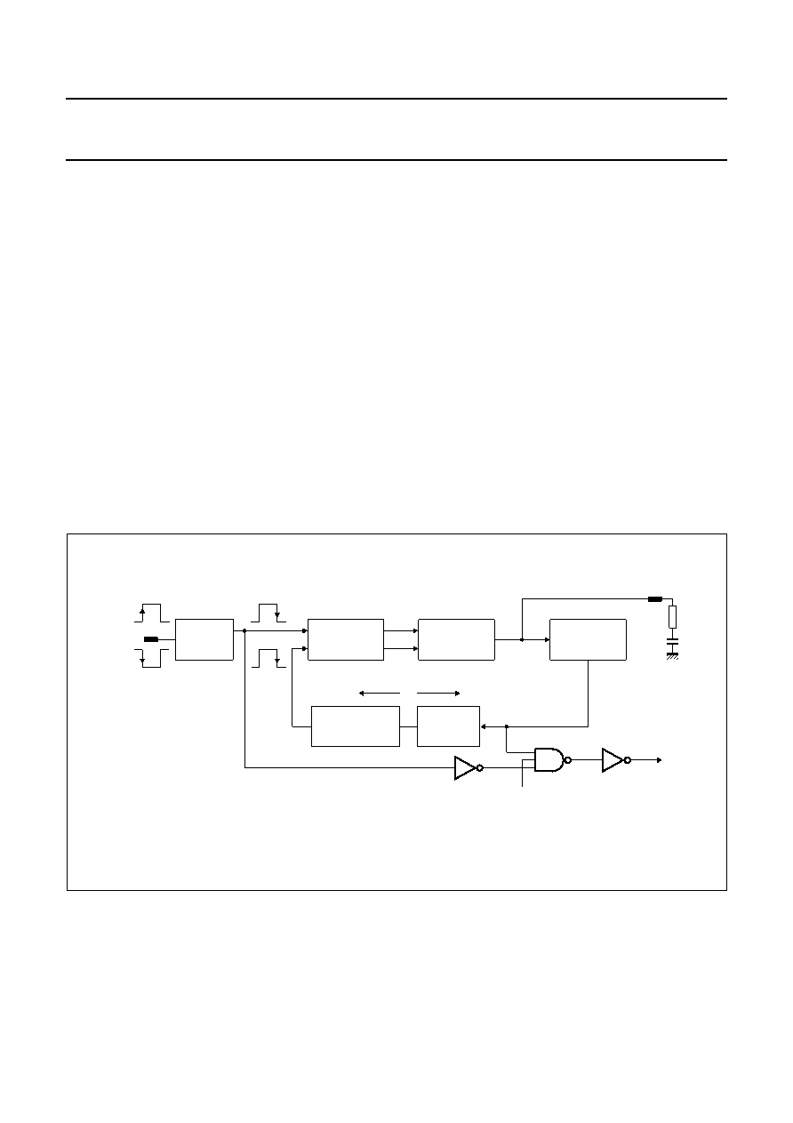
11 OSD CLOCK
The on-chip clock generator comprises Phase-Locked
Loop circuitry and is shown in Fig.39. The frequency of the
OSD clock is programmable and is determined by the
contents of the 6-bit counter, which is loaded using
Command 6. The OSD clock frequency is calculated as
shown below; frequencies within the range 4 to10 MHz
can be selected.
Where: 16 < (PLLCN) < 40; (PLLCN) is the decimal value
held in the 6-bit counter.
The Voltage Controlled Oscillator (VCO) is synchronized
to the HIGH-to-LOW edge of f1 (see Fig.39) which is
always on the traiing edge of fHSYNC. The programmable
active level detector will pass the HSYNC signal if it is
programmed as active HIGH or invert the HSYNC signal if
it is programmed as active LOW. The 4-bit prescaler
increments or decrements the output of the VCO in steps
of (16
× fHSYNC).
f
OSD
f
HSYNC
16
PLLCN
()
×
=
The OSD clock is enabled/disabled using Command 7;
see Section 9.8. When the OSD clock is disabled, the
oscillator remains active, therefore the transient time from
the OSD clock start-up to locking into the external HSYNC
signal is reduced. As the on-chip oscillator is always active
after power-on, when the OSD clock is enabled no large
currents flow (as for RC or LC oscillators); therefore
radiated noise is dramatically reduced.
Character width is a function of the OSD clock frequency;
decreasing fOSD increases the width of the characters.
Therefore, for optimum character display quality the
choice of the OSD clock frequency is important; this is
explained in Chapter 12.
Fig.39 Block diagram of OSD oscillator.
handbook, full pagewidth
MLC349
VOLTAGE
CONTROLLED
OSCILLATOR
CHARGE PUMP
AND
LOOP FILTER
PHASE/
FREQUENCY
DETECTOR
ACTIVE
LEVEL
DETECTOR
PROGRAMMABLE
6-BIT COUNTER
f OSD
divided by N
4-BIT
PRESCALER
HSYNC
OSD disable
f PLL
f 1
C
R1
C1
相關PDF資料 |
PDF描述 |
|---|---|
| 935176920112 | ON-SCREEN DISPLAY IC, PDSO24 |
| 935166800118 | TRIPLE 2-CHANNEL, SGL ENDED MULTIPLEXER, PDSO16 |
| 933715320118 | TRIPLE 2-CHANNEL, SGL ENDED MULTIPLEXER, PDSO16 |
| 933669760652 | TRIPLE 2-CHANNEL, SGL ENDED MULTIPLEXER, PDIP16 |
| 933670390112 | TRIPLE 2-CHANNEL, SGL ENDED MULTIPLEXER, PDIP16 |
相關代理商/技術參數 |
參數描述 |
|---|---|
| 93516-PIX | 制造商:FCI 功能描述: |
| 93517-090001 | 制造商:FCI 功能描述:PCMCIA REV CARD FRAME 9P |
| 93517-150000 | 制造商:FCI 功能描述: |
| 93518097J | 制造商:Fiskars Brands Inc 功能描述:Fiskars 45mm Rotary Blades - Pinking (Fits Models 195800/154570/19680/19583) (Fr |
| 935181002005 | 功能描述:電容套件 HiTmpSilCap Kit 0402 1nF 10nF 33nF BD11V RoHS:否 制造商:Nichicon 電容范圍:10 uF to 680 uF 公差范圍: 電壓范圍:6.3 V to 25 V 產品:Aluminum Organic Polymer Capacitor Kit |
發布緊急采購,3分鐘左右您將得到回復。