- 您現在的位置:買賣IC網 > PDF目錄373916 > AD7751AAN-REF (Analog Devices, Inc.) GT 3C 3#8 SKT RECP PDF資料下載
參數資料
| 型號: | AD7751AAN-REF |
| 廠商: | Analog Devices, Inc. |
| 英文描述: | GT 3C 3#8 SKT RECP |
| 中文描述: | 電能計量IC,帶有片上故障檢測 |
| 文件頁數: | 13/16頁 |
| 文件大小: | 249K |
| 代理商: | AD7751AAN-REF |
REV. A
–13–
AD7751
FREQUENCY
–
Hz
40
P
–
–
0.05
–
0.10
0
0.05
0.10
0.15
0.20
0.25
0.30
45
50
55
60
65
70
Figure 11. Phase Error Between Channels (40 Hz to 70 Hz)
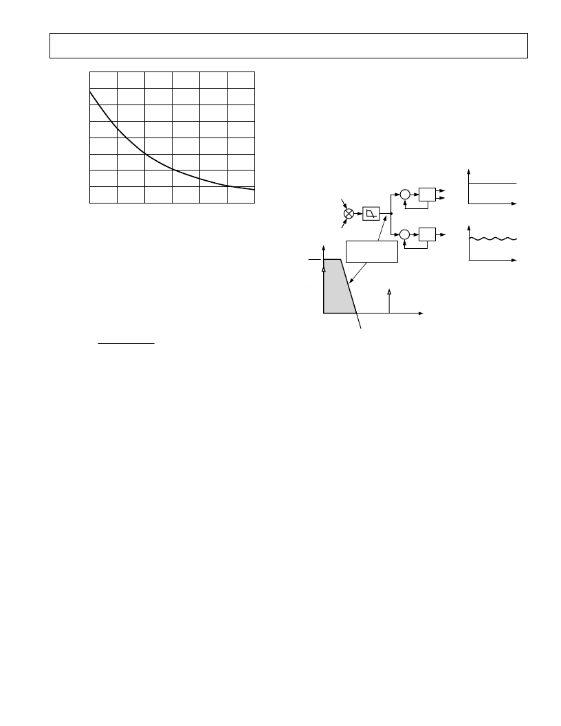
DIGITAL-TO-FREQUENCY CONVERSION
As previously described, the digital output of the low-pass filter
after multiplication contains the real-power information. However,
since this LPF is not an ideal “brick wall” filter implementation,
the output signal also contains attenuated components at
the line frequency and its harmonics, i.e., cos(h
ω
t) where
h = 1, 2, 3, . . . etc.
The magnitude response of the filter is given by:
1
1
| ( )|
H f
( /8 9
f
)
Hz
=
+
(6)
For a line frequency of 50 Hz, this would give an attenuation of
the 2
ω
(100 Hz) component of approximately –22 dBs. The
dominating harmonic will be at twice the line frequency, i.e.,
cos(2
ω
t) and this is due to the instantaneous power signal.
Figure 12 shows the instantaneous real-power signal output of
LPF which still contains a significant amount of instantaneous
power information, i.e., cos(2
ω
t). This signal is then passed to
the digital-to-frequency converter where it is integrated (accumu-
lated) over time in order to produce an output frequency. This
accumulation of the signal will suppress or average out any non-
dc components in the instantaneous real-power signal. The average
value of a sinusoidal signal is zero. Hence the frequency generated
by the AD7751 is proportional to the average real power. Figure
12 shows the digital-to-frequency conversion for steady load
conditions, i.e., constant voltage and current.
As can be seen in the diagram, the frequency output CF is seen
to vary over time, even under steady load conditions. This fre-
quency variation is primarily due to the cos(2
ω
t) component in
the instantaneous real-power signal. The output frequency on CF
can be up to 128 times higher than the frequency on F1 and F2.
This higher output frequency is generated by accumulating the
instantaneous real-power signal over a much shorter time while
converting it to a frequency. This shorter accumulation period
means less averaging of the cos(2
ω
t) component. As a conse-
quence, some of this instantaneous power signal passes through
the digital-to-frequency conversion. This will not be a problem
in the application. Where CF is used for calibration purposes,
the frequency should be averaged by the frequency counter.
This will remove any ripple. If CF is being used to measure energy,
e.g., in a microprocessor-based application, the CF output should
also be averaged to calculate power. However, if an energy
measurement is being made by counting pulses, no averaging is
required. Because the outputs F1 and F2 operate at a much
lower frequency, a lot more averaging of the instantaneous real-
power signal is carried out. The result is a greatly attenuated
sinusoidal content and a virtually ripple-free frequency output.
2
V I
2
FREQUENCY
–
RAD/S
LPF
DIGITAL-TO-
FREQUENCY
F1
F2
DIGITAL-TO-
FREQUENCY
CF
INSTANTANEOUS REAL-POWER SIGNAL
(FREQUENCY DOMAIN)
MULTIPLIER
TIME
FF1
FCF
TIME
V
I
0
LPF TO EXTRACT
REAL POWER
(DC TERM)
cos(2 t)
ATTENUATED BY LPF
Figure 12. Real-Power-to-Frequency Conversion
FAULT DETECTION
The AD7751 incorporates a novel fault detection scheme that
warns of fault conditions and allows the AD7751 to continue
accurate billing during a fault event. The fault detection function is
designed to work over a line frequency of 45 Hz to 55 Hz. The
AD7751 does this by continuously monitoring both the phase
and neutral (return) currents. A fault is indicated when these
currents differ by more than 12.5%. However, even during a
fault the output pulse rate on F1 and F2 is generated using the
larger of the two currents. Because the AD7751 looks for a
difference between the signals on V1A and V1B, it is important
that both current transducers are closely matched.
On power-up the output pulse rate of the AD7751 is proportional
to the product of the signals on Channel V1A and Channel 2. If
there is a difference of greater than 12.5% between V1A and
V1B on power-up, the fault indicator (FAULT) will go active
after about one second. In addition, if V1B is greater than V1A
the AD7751 will select V1B as the input. The fault detection is
automatically disabled when the voltage signal on Channel 1 is less
than 0.5% of the full-scale input range. This will eliminate false
detection of a fault due to noise at light loads.
相關PDF資料 |
PDF描述 |
|---|---|
| AD7751ABRS | ECONOLINE: RB & RA - Dual Output from a Single Input Rail- Power Sharing on Output- Industry Standard Pinout- 1kVDC & 2kVDC Isolation- Custom Solutions Available- UL94V-0 Package Material- Efficiency to 85% |
| AD7751AAN | Energy Metering IC With On-Chip Fault Detection |
| AD7751AARS | Energy Metering IC With On-Chip Fault Detection |
| AD7755AAN-REF | GT 7C 7#8 SKT RECP |
| AD7755AARS | Energy Metering IC with Pulse Output |
相關代理商/技術參數 |
參數描述 |
|---|---|
| AD7751AARS | 制造商:Rochester Electronics LLC 功能描述:PRODUCT TO FREQUENCY CONV - Bulk |
| AD7751ABRS | 制造商:AD 制造商全稱:Analog Devices 功能描述:Energy Metering IC With On-Chip Fault Detection |
| AD7751AN | 制造商:Rochester Electronics LLC 功能描述:PRODUCT TO FREQUENCY CONV - Bulk |
| AD7751ARS | 制造商:Rochester Electronics LLC 功能描述:- Bulk 制造商:Analog Devices 功能描述: |
| AD7751BRS | 制造商:未知廠家 制造商全稱:未知廠家 功能描述:Power Metering |
發布緊急采購,3分鐘左右您將得到回復。