- 您現(xiàn)在的位置:買賣IC網(wǎng) > PDF目錄373922 > AD7873BCP (ANALOG DEVICES INC) Touch Screen Digitizer PDF資料下載
參數(shù)資料
| 型號: | AD7873BCP |
| 廠商: | ANALOG DEVICES INC |
| 元件分類: | 消費家電 |
| 英文描述: | Touch Screen Digitizer |
| 中文描述: | SPECIALTY CONSUMER CIRCUIT, QCC16 |
| 封裝: | 4 X 4 MM, MO-220VGGC, LFCSP-16 |
| 文件頁數(shù): | 19/28頁 |
| 文件大小: | 657K |
| 代理商: | AD7873BCP |
第1頁第2頁第3頁第4頁第5頁第6頁第7頁第8頁第9頁第10頁第11頁第12頁第13頁第14頁第15頁第16頁第17頁第18頁當前第19頁第20頁第21頁第22頁第23頁第24頁第25頁第26頁第27頁第28頁
AD7873
CONTROL REGISTER
The control word provided to the ADC via the DIN pin is
shown in Table 6. This provides the conversion start, channel
addressing, ADC conversion resolution, configuration, and
power-down of the AD7873.
Rev. D | Page 19 of 28
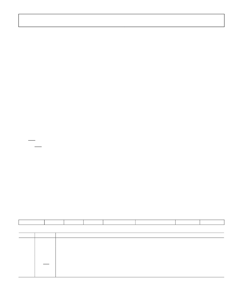
Table 6
provides detailed information on the order and
description of these control bits within the control word.
Initiate START
The first bit, the S bit, must always be set to 1 to initiate the start
of the control word. The AD7873 ignores any inputs on the DIN
line until the start bit is detected.
Channel Addressing
The next three bits in the control register, A2, A1, and A0, select
the active input channel(s) of the input multiplexer (see Table 5
and Figure 26), touch screen drivers, and the reference inputs.
Mode
The MODE bit sets the resolution of the analog-to-digital
converter. With a 0 in this bit, the following conversion has
12 bits of resolution. With a 1 in this bit, the following
conversion has 8 bits of resolution.
SER/DFR
The SER/DFR bit controls the reference mode, which can be
either single-ended or differential if a 1 or a 0 is written to this
bit respectively. The differential mode is also referred to as the
ratiometric conversion mode. This mode is optimum for
X-position, Y-position, and pressure-touch measurements. The
reference is derived from the voltage at the switch drivers,
which is almost the same as the voltage to the touch screen. In
this case, a separate reference voltage is not needed because the
reference voltage to the ADC is the voltage across the touch
screen. In single-ended mode, the reference voltage to the
converter is always the difference between the V
REF
and GND
pins. See Table 5 and Figure 26 through Figure 29 for further
information.
If X-position, Y-position, and pressure touch are measured in
single-ended mode, an external reference voltage or +V
CC
is
required for maximum dynamic range. The internal reference
can be used for these single-ended measurements; however, a
loss in dynamic range is incurred. If an external reference is
used, the AD7873 should also be powered from the external
reference. Because the supply current required by the device is
so low, a precision reference can be used as the supply source to
the AD7873. It might also be necessary to power the touch
screen from the reference, which could require 5 mA to 10 mA.
A REF19x voltage reference can source up to 30 mA, and, as
such, could supply both the ADC and the touch screen. Care
must be taken however, to ensure that the input voltage applied
to the ADC does not exceed the reference voltage and therefore
the supply voltage. See the Absolute Maximum Ratings section.
Note that the differential mode can only be used for X-position,
Y-position, and pressure touch measurements. All other
measurements require single-ended mode.
PD0 and PD1
The power management options are selected by programming
the power management bits, PD0 and PD1, in the control
register. Table 7 summarizes the options available and the
internal reference voltage configurations. The internal reference
can be turned on or off independent of the analog-to-digital
converter, allowing power saving between conversions using the
power management options. On power-up, PD0 defaults to 0,
while PD1 defaults to 1.
Table 6. Control Register Bit Function Description
MSB
S
A2
A1
A0
MODE
SER/DFR
PD1
LSB
PD0
Bit No.
7
Mnemonic Comment
S
Start Bit. The control word starts with the first high bit on DIN. A new control word can start every 15th DCLK cycle
when in the 12-bit conversion mode or every 11th DCLK cycle when in 8-bit conversion mode.
Channel Select Bits. These three address bits along with the SER/DFR bit control the setting of the multiplexer
input, switches, and reference inputs, as detailed in Table 5.
12-Bit/8-Bit Conversion Select Bit. This bit controls the resolution of the following conversion. With a 0 in this bit,
the conversion has 12-bit resolution or, with a 1 in this bit, 8-bit resolution.
Single-Ended/Differential Reference Select Bit. Along with Bits A2–A0, this bit controls the setting of the
multiplexer input, switches, and reference inputs as described in Table 5.
Power Management Bits. These two bits decode the power-down mode of the AD7873 as shown in Table 7.
6–4
A2–A0
3
MODE
2
SER/DFR
1, 0
PD1, PD0
相關PDF資料 |
PDF描述 |
|---|---|
| AD7873BRQ | Touch Screen Digitizer |
| AD7874 | 4-Channel, 12-Bit Simultaneous Sampling Data Acquisition System(LC2MOS 4通道,12位同時采樣DAS) |
| AD7878SQ | IC 1:10 CLOCK DRIVER 20-QSOP |
| AD7878 | LC2MOS Complete 12-Bit 100 kHz Sampling ADC with DSP Interface |
| AD7878AQ | LC2MOS Complete 12-Bit 100 kHz Sampling ADC with DSP Interface |
相關代理商/技術參數(shù) |
參數(shù)描述 |
|---|---|
| AD7873BCP-REEL | 制造商:Analog Devices 功能描述:TOUCH SCREEN DIGITIZER |
| AD7873BCP-REEL7 | 制造商:Analog Devices 功能描述:TOUCH SCREEN DIGITIZER 制造商:Analog Devices 功能描述:2.7V 12-BIT TOUCH SCREEN DIGITIZER I.C. - Tape and Reel |
| AD7873BCPZ | 制造商:Analog Devices 功能描述:TOUCH SCREEN DIGITIZER |
| AD7873BRQ | 制造商:Analog Devices 功能描述:TOUCH SCREEN DIGITIZER |
| AD7873BRQ-REEL | 制造商:Analog Devices 功能描述:TOUCH SCREEN DIGITIZER |
發(fā)布緊急采購,3分鐘左右您將得到回復。