- 您現在的位置:買賣IC網 > PDF目錄373938 > AD8132ARM-REEL7 (ANALOG DEVICES INC) Low-Cost, High-Speed Differential Amplifier PDF資料下載
參數資料
| 型號: | AD8132ARM-REEL7 |
| 廠商: | ANALOG DEVICES INC |
| 元件分類: | 音頻/視頻放大 |
| 英文描述: | Low-Cost, High-Speed Differential Amplifier |
| 中文描述: | 1 CHANNEL, VIDEO AMPLIFIER, PDSO8 |
| 封裝: | MO-187AA, MSOP-8 |
| 文件頁數: | 18/20頁 |
| 文件大小: | 391K |
| 代理商: | AD8132ARM-REEL7 |
REV. 0
AD8132
–18–
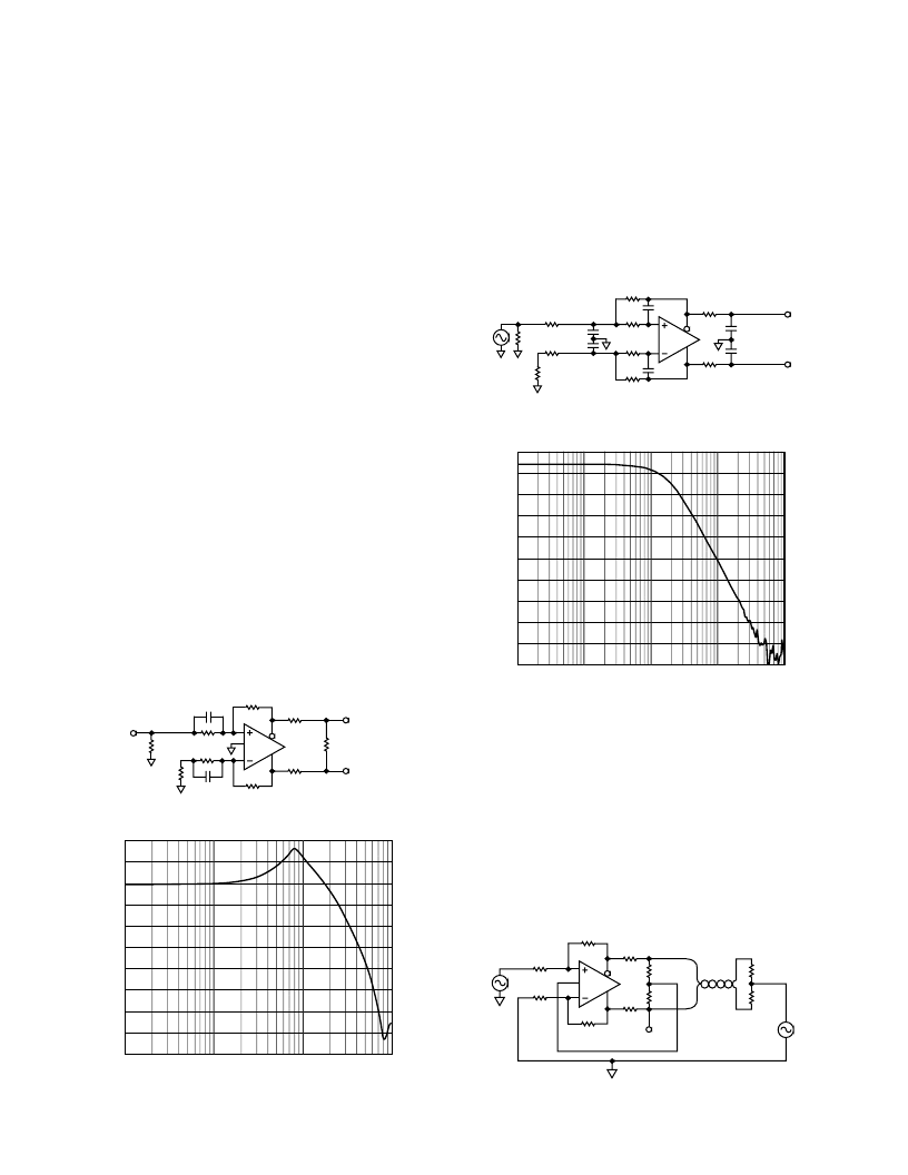
Low-Pass Differential Filter
Similar to an op amp, various types of active
fi
lters can be cre-
ated with the AD8132. These can have single-ended inputs and
differential outputs, which can provide an antialias function
when driving a differential A/D converter.
Figure 14 is a schematic of a low-pass, multiple-feedback
fi
lter.
The active section contains two poles, and an additional pole is
added at the output. The
fi
lter was designed to have a
–
3 dB
frequency of 1 MHz. The actual
–
3 dB frequency was measured
to be 1.12 MHz as shown in Figure 15.
33pF
2.15k
953
953
33pF
2.15k
100pF
100pF
2k
2k
24.9
49.9
549
549
200pF
200pF
V
IN
V
OUT
Figure 14. 1 MHz, 3-Pole Differential Output Low-Pass
Multiple Feedback Filter
FREQUENCY
–
Hz
10
10k
0
–
10
–
20
–
30
–
40
–
50
–
60
–
70
–
80
–
90
100k
1M
10M
100M
V
O
/
I
–
Figure 15. Frequency Response of 1 MHz Low-Pass Filter
High Common-Mode-Output-Impedance Amplifier
Changing the connection to V
OCM
(Pin 2) can change the
common-mode from low impedance to high impedance. If
V
OCM
is actively set to a particular voltage, the AD8132 will try
to force V
OUT,cm
to the same voltage with a relatively low output
impedance. All the previous analysis assumed that this output
impedance is arbitrarily low enough to drive the load condition
in the circuit.
However, the are some applications that bene
fi
t from a high
common-mode output impedance. This can be accomplished
with the circuit shown in Figure 16.
R
G
348
R
F
348
R
F
348
R
G
348
10
10
1k
1k
49.9
49.9
Figure 16. High Common-Mode Output Impedance Differ-
ential Amplifier
The complementary electrical
fi
elds will mostly be con
fi
ned to
the space between the two twisted conductors and will not sig-
ni
fi
cantly radiate out from the cable. The current in the cable will
create magnetic
fi
elds that will radiate to some degree. However,
the amount of radiation is mitigated by the twists, because for
each twist, the two adjacent twists will have an opposite polarity
magnetic
fi
eld. If the twist pitch is tight enough, these small
magnetic
fi
eld loops will contain most of the magnetic flux,
and the magnetic far-
fi
eld strength will be negligible.
Any imbalance in the differential drive signal will appear as a
common-mode signal on the cable. This is the equivalent of a
single wire that is driven with the common-mode signal. In this
case, the wire will act as an antenna and radiate. Thus, in order
to minimize radiation when driving differential twisted pair
cables, the differential drive signal should be very well balanced.
The common-mode feedback loop in the AD8132 helps to
minimize the amount of common-mode voltage at the output,
and can therefore be used to create a well-balanced differential
line driver. Figure 11 shows an application that uses an AD8132
as a balanced line driver and AD830 as a differential receiver
con
fi
gured for unity gain. This circuit was operated with 10 m
of Category 5 cable.
Transmit Equalizer
Any length of transmission line will attenuate the signals it carries.
This effect is worse at higher frequencies than at low frequen-
cies. One way to compensate for this is to provide an equalizer
circuit that boosts the higher frequencies in the transmitter
circuit, so that at the receive end of the cable, the attenuation
effects are diminished.
By lowering the impedance of the R
G
component of the feed-
back network at higher frequency, the gain can be increased at
high frequency. Figure 12 shows a gain-of-two line driver that
has its R
G
s shunted by 10 pF resistors. The effect of this is shown
in the frequency response plot of Figure 13.
249
249
49.9
10pF
499
10pF
24.9
V
IN
49.9
499
49.9
100
V
OUT
Figure 12. Frequency Boost Circuit
1
1000
20
10
0
–
10
–
20
–
30
–
40
–
50
–
60
–
70
–
80
V
O
/
I
–
10
100
FREQUENCY
–
MHz
Figure 13. Frequency Response for Transmit Boost Circuit
相關PDF資料 |
PDF描述 |
|---|---|
| AD8133 | Triple Differential Driver With Output Pull-Down |
| AD8133ACP-REEL | Triple Differential Driver With Output Pull-Down |
| AD8133ACP-REEL7 | Triple Differential Driver With Output Pull-Down |
| AD8133ACPZ-REEL | Triple Differential Driver With Output Pull-Down |
| AD8133ACPZ-REEL7 | Triple Differential Driver With Output Pull-Down |
相關代理商/技術參數 |
參數描述 |
|---|---|
| AD8132ARMZ | 功能描述:IC AMP DIFF LDIST LP 70MA 8MSOP RoHS:是 類別:集成電路 (IC) >> Linear - Amplifiers - Instrumentation 系列:- 產品培訓模塊:Differential Circuit Design Techniques for Communication Applications 標準包裝:1 系列:- 放大器類型:RF/IF 差分 電路數:1 輸出類型:差分 轉換速率:9800 V/µs 增益帶寬積:- -3db帶寬:2.9GHz 電流 - 輸入偏壓:3µA 電壓 - 輸入偏移:- 電流 - 電源:40mA 電流 - 輸出 / 通道:- 電壓 - 電源,單路/雙路(±):3 V ~ 3.6 V 工作溫度:-40°C ~ 85°C 安裝類型:表面貼裝 封裝/外殼:16-VQFN 裸露焊盤,CSP 供應商設備封裝:16-LFCSP-VQ 包裝:剪切帶 (CT) 產品目錄頁面:551 (CN2011-ZH PDF) 其它名稱:ADL5561ACPZ-R7CT |
| AD8132ARMZ | 制造商:Analog Devices 功能描述:IC - Differential Amplifier 制造商:Analog Devices 功能描述:IC, DIFF AMP, 350MHZ, 1200V/ uS, MSOP-8 |
| AD8132ARMZ1 | 制造商:AD 制造商全稱:Analog Devices 功能描述:Low Cost, High Speed Differential Amplifier |
| AD8132ARMZ-REEL | 功能描述:IC AMP DIFF LDIST LP 70MA 8MSOP RoHS:是 類別:集成電路 (IC) >> Linear - Amplifiers - Instrumentation 系列:- 標準包裝:50 系列:- 放大器類型:通用 電路數:2 輸出類型:滿擺幅 轉換速率:1.8 V/µs 增益帶寬積:6.5MHz -3db帶寬:4.5MHz 電流 - 輸入偏壓:5nA 電壓 - 輸入偏移:100µV 電流 - 電源:65µA 電流 - 輸出 / 通道:35mA 電壓 - 電源,單路/雙路(±):1.8 V ~ 5.25 V,±0.9 V ~ 2.625 V 工作溫度:-40°C ~ 85°C 安裝類型:表面貼裝 封裝/外殼:10-TFSOP,10-MSOP(0.118",3.00mm 寬) 供應商設備封裝:10-MSOP 包裝:管件 |
| AD8132ARMZ-REEL1 | 制造商:AD 制造商全稱:Analog Devices 功能描述:Low Cost, High Speed Differential Amplifier |
發布緊急采購,3分鐘左右您將得到回復。