- 您現(xiàn)在的位置:買賣IC網(wǎng) > PDF目錄373944 > AD8344ACPZ-REEL7 (ANALOG DEVICES INC) Active Receive Mixer 400 MHz to 1.2 GHz PDF資料下載
參數(shù)資料
| 型號: | AD8344ACPZ-REEL7 |
| 廠商: | ANALOG DEVICES INC |
| 元件分類: | 衰減器 |
| 英文描述: | Active Receive Mixer 400 MHz to 1.2 GHz |
| 中文描述: | 400 MHz - 1200 MHz RF/MICROWAVE DOUBLE BALANCED MIXER |
| 封裝: | 3 X 3 MM, LEAD FREE, LFCSP-16 |
| 文件頁數(shù): | 15/20頁 |
| 文件大小: | 429K |
| 代理商: | AD8344ACPZ-REEL7 |
AD8344
The high input impedance of the AD8351 allows for a shunt
differential termination to provide the desired 200 load to the
AD8344 IF output port.
Rev. 0 | Page 15 of 20
It is necessary to bias the open collector outputs using one of
the schemes presented in Figure 39 and Figure 40. Figure 39
illustrates the application of a center-tapped impedance trans-
former. The turns ratio of the transformer should be selected to
provide the desired impedance transformation. In the case of a
50 load impedance, a 4-to-1 impedance ratio transformer
should be used to transform the 50 load into a 200
differential load at the IF output pins. Figure 40 illustrates a
differential IF interface where pull-up choke inductors are used
to bias the open-collector outputs. The shunting impedance of
the choke inductors used to couple dc current into the mixer
core should be large enough at the IF frequency of operation as
to not load down the output current before reaching the
intended load. Additionally, the dc current handling capability
of the selected choke inductors needs to be at least 45 mA. The
self resonant frequency of the selected choke should be higher
than the intended IF frequency. A variety of suitable choke
inductors are commercially available from manufacturers such
as Murata and Coilcraft. An impedance transforming network
may be required to transform the final load impedance to 200
at the IF outputs. There are several good reference books that
explain general impedance matching procedures, including:
Chris Bowick,
RF Circuit Design
, Newnes, Reprint Edition,
1997.
David M. Pozar,
Microwave Engineering
, Wiley Text Books,
Second Edition, 1997.
Guillermo Gonzalez,
Microwave Transistor Amplifiers: Analy-
sis and Design
, Prentice Hall, Second Edition, 1996.
0
COMM
8
IFOP
7
IFOM
6
COMM
5
AD8344
Z
L
= 200
IF OUT
Z
O
= 50
+V
S
4:1
Figure 39. Biasing the IF Port Open Collector Outputs
Using a Center-Tapped Impedance Transformer
0
COMM
8
IFOP
7
IFOM
6
COMM
5
AD8344
RFC
+V
S
RFC
Z
L
= 200
IF OUT+
IF OUT–
+V
S
Z
L
IMPEDANCE
TRANSFORMING
NETWORK
Figure 40. Biasing the IF Port Open Collector Outputs
Using Pull-Up Choke Inductors
0
0
180
30
330
50MHz
50MHz
IDEAL
CHOKES
500MHz
500MHz
60
90
270
300
120
240
150
210
REAL
CHOKES
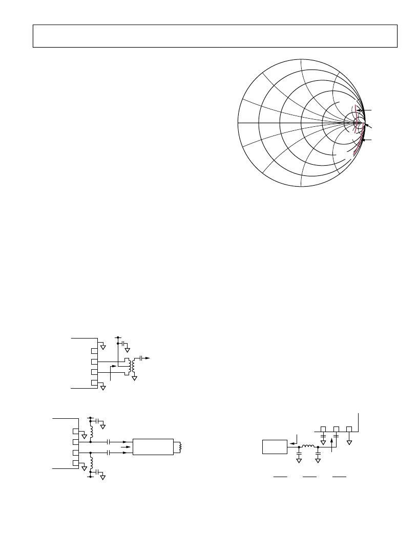
Figure 41. IF Port Loading Effects due to Finite-Q Pull-Up Inductors
(Murata BLM18HD601SN1D Chokes)
LO CONSIDERATIONS
The LO signal needs to have adequate phase noise characteris-
tics and reasonable low second harmonic content to prevent
degradation of the noise figure performance of the AD8344. A
LO plagued with poor phase noise can result in reciprocal
mixing, a mechanism that causes spectral spreading of the
downconverted signal, limiting the sensitivity of the mixer at
frequencies close-in to any large input signals. The internal LO
buffer provides enough gain to hard limit the input LO and
provide fast switching of the mixer core. Odd harmonic content
present on the LO drive signal should not impact mixer
performance; however, even-order harmonics cause the mixer
core to commutate in an unbalanced manner, potentially
degrading noise performance. Simple lumped element low-pass
filtering can be applied to help reject the harmonic content of a
given local oscillator, as illustrated in Figure 42. The filter
depicted is a common 3-pole Chebyshev, designed to maintain a
1-to-1 source-to-load impedance ratio with no more than
0.5 dB of ripple in the pass band. Other filter structures can be
effective as long as the second harmonic of the LO is filtered to
negligible levels, e.g., ~30 dB below the fundamental. The meas-
ured frequency response of the Chebyshev filter for a 1200 MHz
3 dB cutoff frequency is presented in Figure 43.
0
AD8344
LOIN
3
COMM
4
LOCM
2
R
L
FOR R
S
= R
L
L2 =12
L
f
C
- FILTER CUTOFF FREQUENCY
R
S
C1
C3
LO
SOURCE
L2
C1 =
1.864
2
π
f
cR
L
C3 =
1.834
2
π
f
cR
L
π
f
c
Figure 42. Using a Low-Pass Filter to Reduce LO Second Harmonic
相關(guān)PDF資料 |
PDF描述 |
|---|---|
| AD8344ACPZ-WP | Active Receive Mixer 400 MHz to 1.2 GHz |
| AD8345ARE-REEL | 250 MHz.1000 MHz Quadrature Modulator |
| AD8345ARE-REEL7 | 250 MHz.1000 MHz Quadrature Modulator |
| AD8345 | 250 MHz.1000 MHz Quadrature Modulator |
| AD8345-EVAL | 250 MHz.1000 MHz Quadrature Modulator |
相關(guān)代理商/技術(shù)參數(shù) |
參數(shù)描述 |
|---|---|
| AD8344ACPZ-WP | 制造商:Analog Devices 功能描述:UP/DOWN CONV MIXER 5V 1.2GHZ 16LFCSP EP - Waffle Pack |
| AD8344-EVAL | 制造商:Analog Devices 功能描述:Evaluation Kit For Active Receive Mixer 制造商:Analog Devices 功能描述:EVAL KIT FOR ACTV RECEIVE MIXER - Bulk |
| AD8344-EVALZ | 功能描述:EVAL BOARD FOR AD8344 制造商:analog devices inc. 系列:- 零件狀態(tài):在售 類型:混頻器 頻率:400MHz ~ 1.2GHz 配套使用產(chǎn)品/相關(guān)產(chǎn)品:AD8344 所含物品:板 標(biāo)準(zhǔn)包裝:1 |
| AD8345 | 制造商:AD 制造商全稱:Analog Devices 功能描述:250 MHz.1000 MHz Quadrature Modulator |
| AD8345ARE | 功能描述:IC QUADRATURE MOD 250MHZ 16TSSOP RoHS:否 類別:RF/IF 和 RFID >> RF 調(diào)制器 系列:- 產(chǎn)品培訓(xùn)模塊:Lead (SnPb) Finish for COTS Obsolescence Mitigation Program 標(biāo)準(zhǔn)包裝:2,500 系列:- 功能:調(diào)制器 LO 頻率:700MHz ~ 2.3GHz RF 頻率:700MHz ~ 2.3GHz P1dB:1dBm 底噪:-148dBm/Hz 輸出功率:-1dBm 電流 - 電源:46mA 電源電壓:2.7 V ~ 3.6 V 測試頻率:1.75GHz 封裝/外殼:28-WFQFN 裸露焊盤 包裝:帶卷 (TR) |
發(fā)布緊急采購,3分鐘左右您將得到回復(fù)。