- 您現在的位置:買賣IC網 > PDF目錄373952 > AD8644 (Analog Devices, Inc.) Single and Quad +18 V Operational Amplifiers PDF資料下載
參數資料
| 型號: | AD8644 |
| 廠商: | Analog Devices, Inc. |
| 英文描述: | Single and Quad +18 V Operational Amplifiers |
| 中文描述: | 單路和四路運算放大器18 V |
| 文件頁數: | 5/8頁 |
| 文件大小: | 303K |
| 代理商: | AD8644 |
AD8614/AD8644
–5–
REV. 0
SUPPLY VOLTAGE – V
0
2
20
4
6
8
10
12
14 16
18
S
m
s
9
8
0
4
3
2
1
7
5
6
A
V
= 1
R
L
= 2k
V
C
L
= 200pF
T
A
= 25
8
C
SR+
SR
2
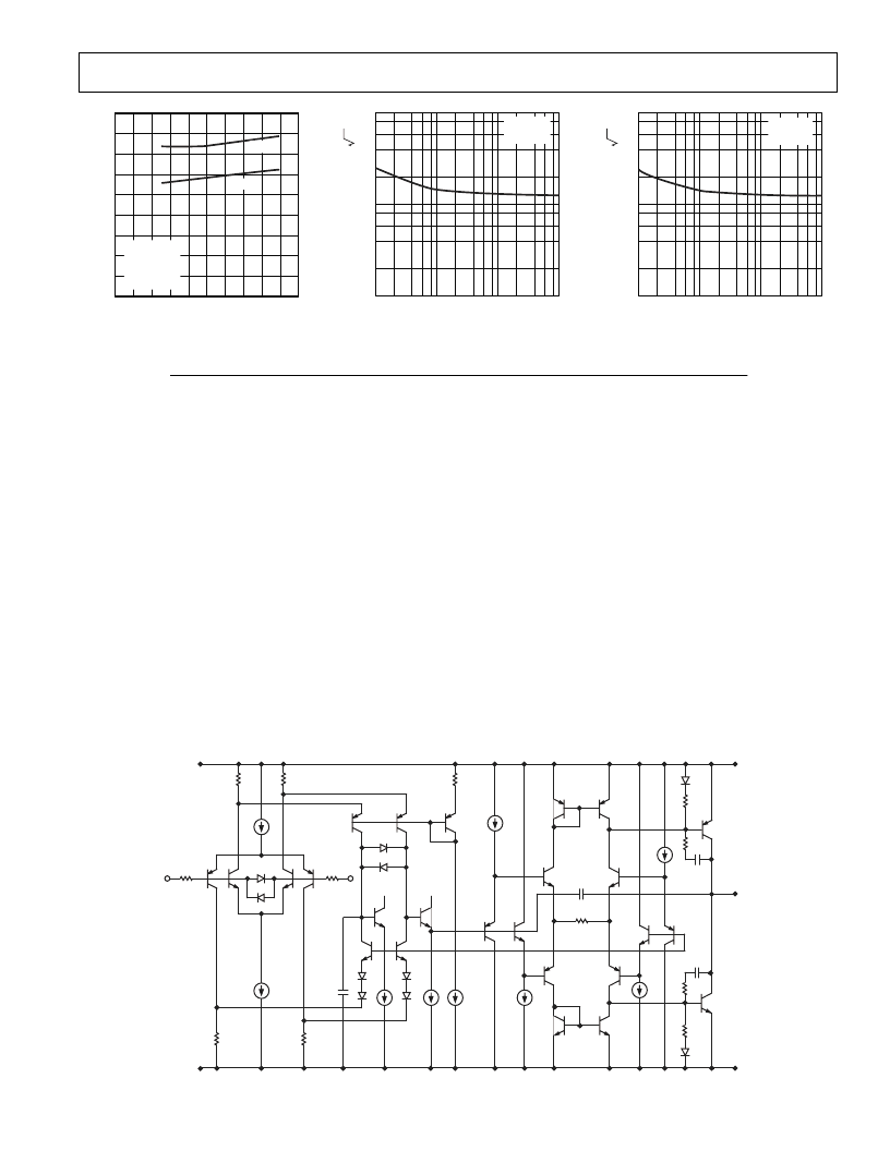
Figure 19. Slew Rate vs. Supply
Voltage
V
FREQUENCY – Hz
100
10
110
100
10k
1k
V
S
= 5V
T
A
= 25
8
C
Figure 20. Voltage Noise Density
vs. Frequency
V
FREQUENCY – Hz
100
10
110
100
10k
1k
V
S
= 18V
T
A
= 25
8
C
Figure 21. Voltage Noise Density vs.
Frequency
APPLICATIONS SECTION
Theory of Operation
The AD8614/AD8644 are processed using Analog Devices’ high
voltage, high speed, complementary bipolar process—HV XFCB.
This process includes trench isolated transistors that lower parasitic
capacitance.
Figure 22 shows a simplified schematic of the AD8614/AD8644.
The input stage is rail-to-rail, consisting of two complementary
differential pairs, one NPN pair and one PNP pair. The input stage
is protected against avalanche breakdown by two back-to-back
diodes. Each input has a 1.5 k
resistor that limits input current
during over-voltage events and furnishes phase reversal protection
if the inputs are exceeded. The two differential pairs are connected
to a double-folded cascode. This is the stage in the amplifier with
the most gain. The double folded cascode differentially feeds the
output stage circuitry. Two complementary common emitter tran-
sistors are used as the output stage. This allows the output to swing
to within 125 mV from each rail with a 10 mA load. The gain of the
output stage, and thus the open loop gain of the op amp, depends on
the load resistance.
V
CC
2
+
1.5k
V
V
EE
V
CC
V
OUT
1.5k
V
V
CC
Figure 22. Simplified Schematic
The AD8614/AD8644 have no built-in short circuit protection.
The short circuit limit is a function of high current roll-off of the
output stage transistors and the voltage drop over the resistor
shown on the schematic at the output stage. The voltage over this
resistor is clamped to one diode during short circuit voltage events.
Output Short-Circuit Protection
To achieve a wide bandwidth and high slew rate, the output of
the AD8614/AD8644 is not short-circuit protected. Shorting
the output directly to ground or to a supply rail may destroy the
device. The typical maximum safe output current is 70mA.
In applications where some output current protection is needed,
but not at the expense of reduced output voltage headroom, a low
value resistor in series with the output can be used. This is shown
in Figure 23. The resistor is connected within the feedback loop
of the amplifier so that if V
OUT
is shorted to ground and V
IN
swings up to 18 V, the output current will not exceed 70 mA.
For 18 V single supply applications, resistors less than 261
are
not recommended.
相關PDF資料 |
PDF描述 |
|---|---|
| AD8644AR2 | Single and Quad +18 V Operational Amplifiers |
| AD8644ARU | Single and Quad +18 V Operational Amplifiers |
| AD8615 | Precision 20 MHz CMOS Rail-to-Rail Input/Output Operational Amplifiers |
| AD8615ARJ | Precision 20 MHz CMOS Rail-to-Rail Input/Output Operational Amplifiers |
| AD8618 | Precision 20 MHz CMOS Rail-to-Rail Input/Output Operational Amplifiers |
相關代理商/技術參數 |
參數描述 |
|---|---|
| AD8644AR | 制造商:Analog Devices 功能描述:OP Amp Quad GP R-R I/O 18V 14-Pin SOIC N 制造商:Rochester Electronics LLC 功能描述:QUAD 18V LCD DRIVER - Bulk |
| AD8644AR2 | 制造商:AD 制造商全稱:Analog Devices 功能描述:Single and Quad +18 V Operational Amplifiers |
| AD8644AR-REEL | 制造商:Analog Devices 功能描述:OP Amp Quad GP R-R I/O 18V 14-Pin SOIC N T/R |
| AD8644AR-REEL7 | 制造商:Analog Devices 功能描述:OP Amp Quad GP R-R I/O 18V 14-Pin SOIC N T/R |
| AD8644ARU | 制造商:Analog Devices 功能描述:OP Amp Quad GP R-R I/O 18V 14-Pin TSSOP 制造商:Rochester Electronics LLC 功能描述:QUAD 18V LCD DRIVER - Bulk |
發布緊急采購,3分鐘左右您將得到回復。