- 您現在的位置:買賣IC網 > PDF目錄373963 > AD9483KS-140 (ANALOG DEVICES INC) Triple 8-Bit, 140 MSPS A/D Converter PDF資料下載
參數資料
| 型號: | AD9483KS-140 |
| 廠商: | ANALOG DEVICES INC |
| 元件分類: | ADC |
| 英文描述: | Triple 8-Bit, 140 MSPS A/D Converter |
| 中文描述: | 3-CH 8-BIT FLASH METHOD ADC, PARALLEL ACCESS, PQFP100 |
| 封裝: | HEAT SINK, PLASTIC, MQFP-100 |
| 文件頁數: | 16/26頁 |
| 文件大小: | 319K |
| 代理商: | AD9483KS-140 |

AD9483
–16–
REV. A
EVALUATION BOARD
The AD9483 evaluation board offers an easy way to test the
AD9483. It provides ac or dc biasing for the analog input, it
generates the output latch clocks for Single Mode, Dual
Parallel Mode and Dual Interleaved Mode. Each of the three
channels has a reconstruction DAC (A Port only). The board
has several different modes of operation, and is shipped in
the following configuration:
Single-ended ac coupled analog input (1 V p-p centered
at ground)
Differential clock inputs (PECL) (See ENCODE section
for TTL drive)
Internal voltage references connected to externally buff-
ered on-chip reference (VREF OUT)
Preset for Dual Mode Interleaved
Analog Input
The evaluation board accepts a 1 V p-p input signal centered
at ground for ac coupled input mode (Set Jumpers W4, W5,
W12, W13, W18, W17 to jump Pin 1 to Pin 2). This signal
biased up to 2.5 V by the on-chip reference. Note: input
signal should be bandlimited (filtered) prior to sampling to
avoid aliasing. The analog inputs are terminated to ground
by a 75
resistor on the board. The analog inputs are ac
coupled through 0.1
μ
F caps C2, C4, C6 on top of the
board. These can be increased to accommodate lower fre-
quency inputs if desired using test points PR1–PR6 on bot-
tom of board. In dc coupled input mode (Set Jumpers W4,
W5, W12, W13, W18, W17 to jump Pin 3 to Pin 2 ) the
board accepts typical video level signal levels (0 mV to 700 mV)
the signal is level shifted and amplified to 1 V p-p by the
AD8055 preamp. Trimpots R98–R100 are used to adjust dc
black level to 2 V at ADC inputs.
Encode
The AD9483 ENCODE input can be driven two ways.
1. Differential PECL (V
LO
= 3, V
HI
= 4 nominal). It is
shipped in this mode.
2. Single ended TTL or CMOS. (At Encode Bar–Remove
50
termination resistor R10, add 0.1
μ
F capacitor C7)
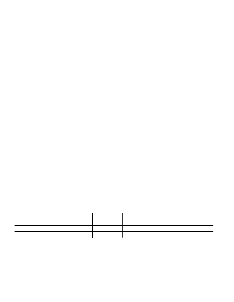
Table III. Evaluation Board Jumper Settings
MODE
W7 (OMS)
W6 (I/P)
W11 (A_LAT)
W11 (B_LAT)
Dual Channel/PARALLEL
LOW
LOW
DATA_CLK_OUT
(4–5)
DATA_CLK_OUT
(2–3)
Dual Channel/INTERLEAVED
LOW
HIGH
DATA_CLK_OUT (5–6)
DATA_CLK_OUT (2–3)
SINGLE
HIGH
DON’T CARE
DATA_CLK_OUT (5–6)
NC
DESIGN NOTES
Maximum frequency for PARALLEL is 140 MHz.
Maximum frequency for INTERLEAVED is 140 MHz.
Maximum frequency for SINGLE is 100 MHz.
DS is tied to ground through a 50
resistor.
DS
is left floating.
Voltage Reference
The AD9483 has an internal 2.5 V voltage reference (VREF
OUT). This is buffered externally on board to support addi-
tional level shifting circuitry (the AD9483 VREF OUT pin can
drive the three VREF IN pins in applications where level shifting
is not required with no additional buffering). An external refer-
ence may be employed instead to drive each VREF IN pin inde-
pendently (requires moving Jumpers W14, W15 and W16).
Single Channel Mode
Single Channel mode sets the AD9483 to produce data on
every clock cycle on output port A only. The maximum speed
in Single Channel mode is 100 MSPS.
Dual Channel Modes (Outputs Clocked at 1/2 Encode Clock)
Dual Channel Interleaved
Sets the ADC to produce data alternately on Port A and Port B.
the maximum speed in this mode is 140 MSPS.
Dual Channel Parallel
Sets the ADC to produce data concurrently on Port A and Port
B. Maximum speed in this mode is 140 MSPS.
DAC Out
The DAC output is a representation of the data on output Port
A only. The DAC is terminated on the board into 75
. Full-
scale voltage swing at DAC output is nominally 0 mV to 800 mV
when terminated into external 75
(doubly terminated).
Output Port B is
not
reconstructed. The DAC outputs are NOT
filtered and will exhibit sampling noise. The DACs can be pow-
ered down at W1, W2, and W3 (jumper not installed).
Data Ready
An output clock for latching the ADC outputs is available at
Pin 1 at the 25-pin connector. Its complement is located at
Pin 14. The clocks are terminated on the board by a 75
Thevenin termination to V
D
/2. The timing on these clock out-
puts can be inverted at W9, W10 (jumper not installed).
Schematics
The schematics for the evaluation board follow. (Note bypass
capacitors for ADC are shown in Figure 39.)
相關PDF資料 |
PDF描述 |
|---|---|
| AD9483 | Triple 8-Bit, 140 MSPS A/D Converter |
| AD9500 | Digitally Programmable Delay Generator |
| AD9500BP | Digitally Programmable Delay Generator |
| AD9500BQ | Digitally Programmable Delay Generator |
| AD9500TE | Digitally Programmable Delay Generator |
相關代理商/技術參數 |
參數描述 |
|---|---|
| AD9484 | 制造商:AD 制造商全稱:Analog Devices 功能描述:8-Bit, 500 MSPS, 1.8 V Analog-to-Digital Converter Excellent linearity |
| AD9484-500EBZ | 功能描述:BOARD EVAL W/AD9484BCPZ-500 RoHS:是 類別:編程器,開發系統 >> 評估板 - 模數轉換器 (ADC) 系列:- 產品培訓模塊:Obsolescence Mitigation Program 標準包裝:1 系列:- ADC 的數量:1 位數:12 采樣率(每秒):94.4k 數據接口:USB 輸入范圍:±VREF/2 在以下條件下的電源(標準):- 工作溫度:-40°C ~ 85°C 已用 IC / 零件:MAX11645 已供物品:板,軟件 |
| AD9484BCPZ-500 | 功能描述:IC ADC 8BIT 500MSPS 56LFCSP RoHS:是 類別:集成電路 (IC) >> 數據采集 - 模數轉換器 系列:- 標準包裝:1 系列:microPOWER™ 位數:8 采樣率(每秒):1M 數據接口:串行,SPI? 轉換器數目:1 功率耗散(最大):- 電壓電源:模擬和數字 工作溫度:-40°C ~ 125°C 安裝類型:表面貼裝 封裝/外殼:24-VFQFN 裸露焊盤 供應商設備封裝:24-VQFN 裸露焊盤(4x4) 包裝:Digi-Reel® 輸入數目和類型:8 個單端,單極 產品目錄頁面:892 (CN2011-ZH PDF) 其它名稱:296-25851-6 |
| AD9484BCPZRL7-500 | 功能描述:IC ADC 8BIT 500MSPS 56LFCSP RoHS:是 類別:集成電路 (IC) >> 數據采集 - 模數轉換器 系列:- 標準包裝:1 系列:- 位數:14 采樣率(每秒):83k 數據接口:串行,并聯 轉換器數目:1 功率耗散(最大):95mW 電壓電源:雙 ± 工作溫度:0°C ~ 70°C 安裝類型:通孔 封裝/外殼:28-DIP(0.600",15.24mm) 供應商設備封裝:28-PDIP 包裝:管件 輸入數目和類型:1 個單端,雙極 |
| AD9500 | 制造商:AD 制造商全稱:Analog Devices 功能描述:Digitally Programmable Delay Generator |
發布緊急采購,3分鐘左右您將得到回復。