- 您現在的位置:買賣IC網 > PDF目錄373974 > ADA4899-1YRDZ-RL (ANALOG DEVICES INC) Unity Gain Stable, Ultralow Distortion, 1 nV/ Hz Voltage Noise, High Speed Op Amp PDF資料下載
參數資料
| 型號: | ADA4899-1YRDZ-RL |
| 廠商: | ANALOG DEVICES INC |
| 元件分類: | 運動控制電子 |
| 英文描述: | Unity Gain Stable, Ultralow Distortion, 1 nV/ Hz Voltage Noise, High Speed Op Amp |
| 中文描述: | OP-AMP, 230 uV OFFSET-MAX, PDSO8 |
| 封裝: | ROHS COMPLIANT, MS-012AA, SOIC-8 |
| 文件頁數: | 15/20頁 |
| 文件大小: | 496K |
| 代理商: | ADA4899-1YRDZ-RL |
ADA4899-1
NOISE
To analyze the noise performance of an amplifier circuit, first
identify the noise sources, then determine if the source has a
significant contribution to the overall noise performance of the
amplifier. To simplify the noise calculations, noise spectral
densities were used, rather than actual voltages to leave
bandwidth out of the expressions (noise spectral density, which
is generally expressed in nV/
√
Hz, is equivalent to the noise in a
1 Hz bandwidth).
Rev. A | Page 15 of 20
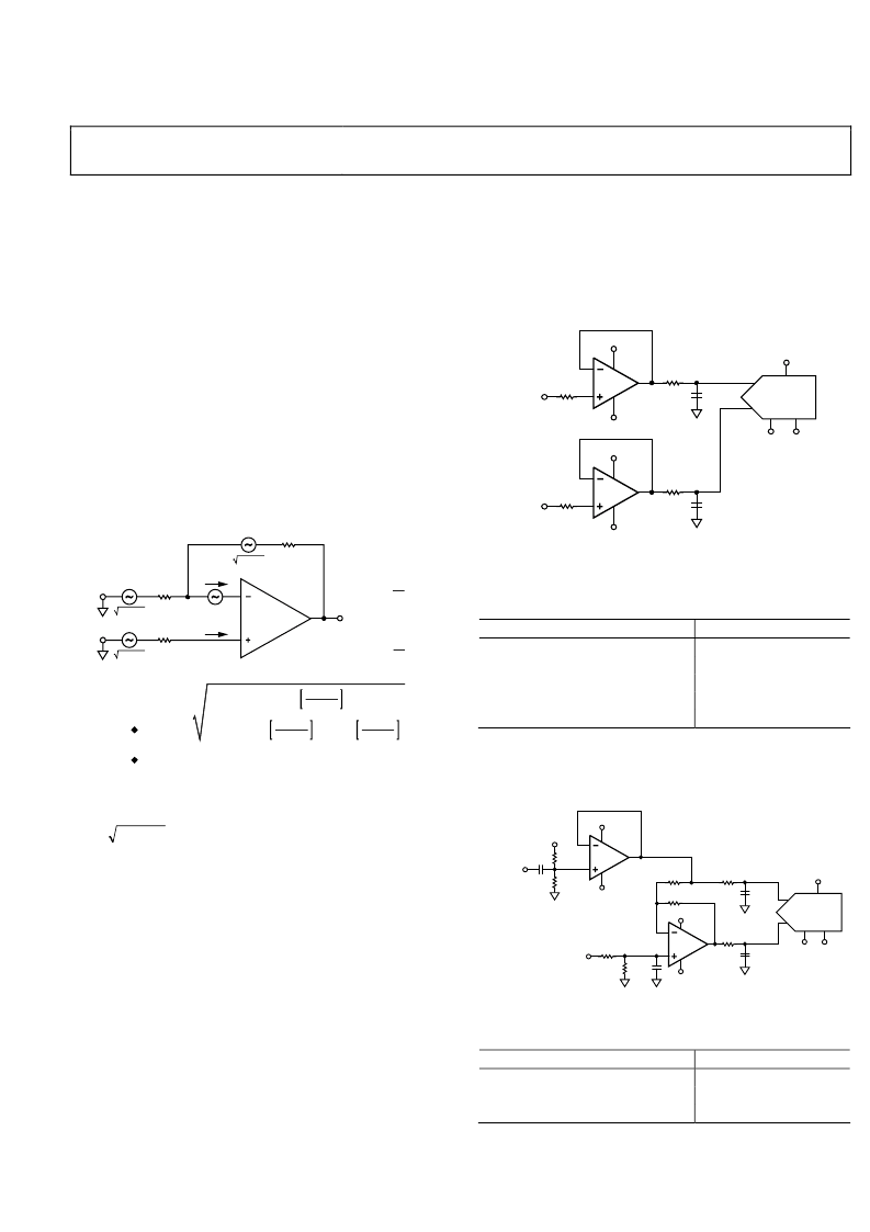
The noise model shown in Figure 48 has six individual noise
sources: the Johnson noise of the three resistors, the op amp
voltage noise, and the current noise in each input of the
amplifier. Each noise source has its own contribution to the
noise at the output. Noise is generally specified referred to input
(RTI), but it is often simpler to calculate the noise referred to
the output (RTO) and then divide by the noise gain to obtain
the RTI noise.
"GAIN FROM
R1
"GAIN FROM
NOISE GAIN =
NG = 1 +R2
I
N–
V
N
V
N, R1
V
N, R3
R1
R2
I
N+
R3
4kTR2
4kTR1
4kTR3
V
N, R2
B
A
V
N2
+ 4kTR3 + 4kTR1 R1 + R2
2
I
N+2
R3
2
+ I
N–2
R1 × R2
2
+ 4kTR2
R1
2
R1 + R2
R1 + R2
RTI NOISE =
RTO NOISE = NG × RTI NOISE
Figure 48. Op Amp Noise Analysis Model
V
OUT
+
0
All resistors have a Johnson noise that is calculated by
)
(4
kBTR
where:
k
is Boltzmann’s Constant (1.38 × 10
–23
J/K).
T
is the absolute temperature in Kelvin.
B
is the bandwidth in Hz.
R
is the resistance in ohms.
A simple relationship that is easy to remember is that a 50 Ω
resistor generates a Johnson noise of 1 nV
√
Hz at 25°C.
In applications where noise sensitivity is critical, care must be
taken not to introduce other significant noise sources to the
amplifier. Each resistor is a noise source. Attention to the
following areas is critical to maintain low noise performance:
design, layout, and component selection. A summary of noise
performance for the amplifier and associated resistors can be
seen in Table 4.
ADC DRIVER
The ultralow noise and distortion performance of the
ADA4899-1 makes it an excellent candidate for driving 16-bit
ADCs. The schematic for a single-ended input buffer using the
ADA4899-1 and the
AD7677
, a 1 MSPS, 16-bit ADC, is shown
in Figure 49. Table 5 shows the performance data of the
ADA4899-1 and the
AD7677
.
0
+5V
ANALOG
INPUT
ADA4899-1
–5V
2.7nF
25
15
+5V
+5V
ANALOG
INPUT
+
–
ADA4899-1
–5V
2.7nF
25
15
AD7677
IN–
IN+
+2.5V
REF
–5V
REF
Figure 49. Single-Ended Input ADC Driver
Table 5. ADA4899-1, Single-Ended Driver for AD7677
16-Bit, 1 MSPS, f
c
= 50 kHz
Parameter
Second Harmonic Distortion
Third Harmonic Distortion
THD
SFDR
SNR
Measurement (dB)
116.5
111.9
108.6
+101.4
+92.6
The ADA4899-1 configured as a single-ended-to-differential
driver for the
AD7677
is shown in Figure 50. Table 6 shows the
associated performance.
0
+5V
+2.5V REF
AINPUT
ADA4899-1
–5V
590
590
+5V
+REF
+2.5V
ADA4899-1
–5V
2.7nF
2.7nF
590
590
590
15
15
590
AD7677
IN–
IN+
REF
+5V
–5V
Figure 50. Single-Ended-to-Differential ADC Driver
Table 6. ADA4899-1, Single Ended-to-Differential Driver for
AD7677 16-Bit, 1 MSPS, f
c
= 500 kHz
Parameter
THD
SFDR
SNR
Measurement (dB)
92.7
+91.8
+90.6
相關PDF資料 |
PDF描述 |
|---|---|
| ADA4922-1 | High Voltage, Differential 18-Bit ADC Driver |
| ADA4922-1ACPZ-R2 | High Voltage, Differential 18-Bit ADC Driver |
| ADA4922-1ACPZ-RL | High Voltage, Differential 18-Bit ADC Driver |
| ADA4922-1ACPZ-RL7 | High Voltage, Differential 18-Bit ADC Driver |
| ADA4922-1ARDZ | High Voltage, Differential 18-Bit ADC Driver |
相關代理商/技術參數 |
參數描述 |
|---|---|
| ADA4922-1 | 制造商:AD 制造商全稱:Analog Devices 功能描述:14-Bit, 1 MSPS, Differential, Programmable Input PulSAR ADC |
| ADA4922-1ACP-EBZ | 功能描述:BOARD EVAL FOR ADA4922-1ACP RoHS:是 類別:編程器,開發系統 >> 評估板 - 運算放大器 系列:- 產品培訓模塊:Lead (SnPb) Finish for COTS Obsolescence Mitigation Program 標準包裝:1 系列:- |
| ADA4922-1ACPZ-R2 | 功能描述:IC ADC DRIVER 18BIT DIFF 8-LFCSP RoHS:是 類別:集成電路 (IC) >> 線性 - 放大器 - 專用 系列:- 產品培訓模塊:Lead (SnPb) Finish for COTS Obsolescence Mitigation Program 標準包裝:60 系列:- 類型:可變增益放大器 應用:CATV 安裝類型:表面貼裝 封裝/外殼:20-WQFN 裸露焊盤 供應商設備封裝:20-TQFN-EP(5x5) 包裝:托盤 |
| ADA4922-1ACPZ-R7 | 制造商:Analog Devices 功能描述:SP AMP DIFF LINE DRVR AMP SGL R-R O/P 26V 8LFCSP EP - Bulk |
| ADA4922-1ACPZ-RL | 功能描述:IC ADC DRIVER 18BIT DIFF 8-LFCSP RoHS:是 類別:集成電路 (IC) >> 線性 - 放大器 - 專用 系列:- 產品培訓模塊:Lead (SnPb) Finish for COTS Obsolescence Mitigation Program 標準包裝:60 系列:- 類型:可變增益放大器 應用:CATV 安裝類型:表面貼裝 封裝/外殼:20-WQFN 裸露焊盤 供應商設備封裝:20-TQFN-EP(5x5) 包裝:托盤 |
發布緊急采購,3分鐘左右您將得到回復。