- 您現在的位置:買賣IC網 > PDF目錄373975 > ADAU1592ACPZ-RL (ANALOG DEVICES INC) Class-D Audio Power Amplifier PDF資料下載
參數資料
| 型號: | ADAU1592ACPZ-RL |
| 廠商: | ANALOG DEVICES INC |
| 元件分類: | 音頻/視頻放大 |
| 英文描述: | Class-D Audio Power Amplifier |
| 中文描述: | 24 W, 2 CHANNEL, AUDIO AMPLIFIER, QCC48 |
| 封裝: | 7 X 7 MM, ROHS COMPLIANT, MO-220VKKD-2, LFCSP-48 |
| 文件頁數: | 15/24頁 |
| 文件大小: | 457K |
| 代理商: | ADAU1592ACPZ-RL |
ADAU1592
THEORY OF OPERATION
OVERVIEW
The ADAU1592 is a 2-channel high performance switching
audio power amplifier. Each of the two Σ-Δ modulators converts
a single-ended analog input into a 2-level PDM output. This
PDM pulse stream is output from the internal full differential
power stage. The ADAU1592 has built-in circuits to suppress the
turn-on and turn-off pop and click. The ADAU1592 also offers
extensive thermal and overcurrent protection circuits.
MODULATOR
The modulator is a 5
th
-order Σ-Δ with feedback from the power
stage connected internally. This helps reduce the external
connections. The 5
th
order modulator switches to a lower order
near full-scale inputs. The modulator gain is optimized at 19 dB
for 15 V operation. The Σ-Δ modulator outputs a pulse density
modulation (PDM) 1-bit stream, which does not produce
distinct sharp peaks and harmonics in the AM band like
conventional fixed-frequency PWM.
The Σ-Δ modulators require feedback to generate PDM stream
with respect to the input. The feedback for the modulators
comes from the power stage. This helps reduce the nonlinearity
in the power stages and achieve excellent THD + N perform-
ance. The feedback also helps in achieving good PSRR. In the
ADAU1592, the feedback from the power stage is internally
connected. This helps reduce the external connections for ease
in PCB layout.
The Σ-Δ modulators operate in a discrete time domain and
Nyquist frequency limit, which is half the sampling frequency.
The modulator uses the master clock of 12.288 MHz. This is
generated by dividing the external clock input by 2. This sets
the f
S
/2 around 6.144 MHz. This is sufficient for the audio
bandwidth of 22 kHz. The modulator shapes the quantization
noise and transfers it outside the audio band. The noise floor
rises sharply above 20 kHz. This ensures very good signal-to-
noise ratio (SNR) in the audio band of 20 kHz. The 6.144 MHz
bandwidth allows the modulator order to be set around the 5
th
order. The modulator uses proprietary dynamic hysteresis to
reduce the switching rate or frequency to around 700 kHz.
This reduces the switching losses and achieves good efficiency.
The dynamic hysteresis helps the modulator to continuously
track the change in PVDD and the input level to keep the
modulator stable.
SLICER
The ADAU1592 has a built-in slicer block following the PGA
and before the modulator. The slicer block is essentially a hard
limiter included for limiting the input signal to the modulator.
This, in turn, limits the output power at a given supply voltage.
The slicer in the ADAU1592 is normally inactive at lower input
levels but is activated as soon as the peak input voltage exceeds
the set threshold. The threshold can be set externally by
connecting a resistor from SLC_TH (Pin 24) to ground. This
Rev. 0 | Page 15 of 24
feature allows the user to adjust the slicer to the desired value
and to limit the output power. For input signals higher than the
set threshold, the slicer clips the input signal to the modulator.
This adds distortion due to clipping of the signal input to the
modulator. This is especially helpful in applications where the
output power available needs to be reduced instead of reducing
the supply voltage.
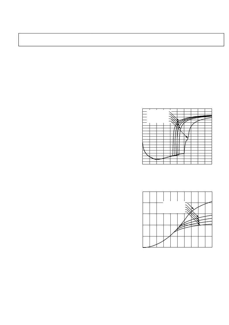
Figure 41 is a plot showing THD + N vs. the input level at 0 dB
PGA, 15 V, and 6 Ω, and demonstrates the difference between a
device with and without the slicer.
–100
0
–95
–90
–85
–80
–75
–70
–65
–60
–55
–50
–45
–40
–35
–30
–25
–20
–15
–10
–5
0
2.0
0.4
0.6
0.8
1.0
1.2
1.4
1.6
1.8
0.2
T
0
INPUT (V rms)
SLICER 1.1V
SLICER 1.17V
SLICER 1.24V
SLICER 1.32V
SLICER DISABLED
Figure 41. THD + N vs. Input Level @ PGA = 0 dB, 15 V
Figure 42 depicts the typical output power vs input at different
slicer settings.
0
25
5
10
15
20
0
2.0
0.4
0.6
0.8
1.0
1.2
1.4
1.6
1.8
0.2
O
0
INPUT (V rms)
SLICER DISABLED
SLICER 1.32V
SLICER 1.24V
SLICER 1.17V
SLICER 1.10V
Figure 42. Typical Output Power vs. Input, at Different Slicer Settings
From Figure 42, it can be seen that the slicer effectively reduces
the output power depending on its setting.
Internally, the slicer block receives the input from the PGA.
Figure 43 shows the block for slicer threshold adjust, SLC_TH
(Pin 24).
相關PDF資料 |
PDF描述 |
|---|---|
| ADAU1592ACPZ-RL7 | Class-D Audio Power Amplifier |
| ADAU1592ASVZ | Class-D Audio Power Amplifier |
| ADAU1592ASVZ-RL | Class-D Audio Power Amplifier |
| ADAU1592ASVZ-RL7 | Class-D Audio Power Amplifier |
| ADAU1702 | SigmaDSP 28-56-Bit Audio Processor with Two ADCs and Four DACs |
相關代理商/技術參數 |
參數描述 |
|---|---|
| ADAU1592ACPZ-RL7 | 功能描述:IC AMP AUDIO PWR 48LFCSP RoHS:是 類別:集成電路 (IC) >> 線性 - 音頻放大器 系列:- 產品培訓模塊:Lead (SnPb) Finish for COTS Obsolescence Mitigation Program 標準包裝:2,500 系列:DirectDrive® 類型:D 類 輸出類型:1-通道(單聲道),帶立體聲耳機 在某負載時最大輸出功率 x 通道數量:930mW x 1 @ 8 歐姆; 40mW x 2 @ 16 歐姆 電源電壓:2.7 V ~ 5.5 V 特點:消除爆音,差分輸入,I²C,靜音,關閉,音量控制 安裝類型:表面貼裝 供應商設備封裝:25-WLP(2.09x2.09) 封裝/外殼:25-WFBGA,WLCSP 包裝:帶卷 (TR) 其它名稱:MAX97000EWA+T-ND |
| ADAU1592ASVZ | 制造商:Analog Devices 功能描述:AMP AUDIO CLASS D SMD TQFPEP-48 |
| ADAU1592ASVZ-RL | 制造商:Analog Devices 功能描述: |
| ADAU1592ASVZ-RL7 | 制造商:Analog Devices 功能描述: |
| ADAU1701 | 制造商:AD 制造商全稱:Analog Devices 功能描述:SigmaDSP 28/56-Bit Audio Processor with 2ADC/4DAC |
發布緊急采購,3分鐘左右您將得到回復。