- 您現(xiàn)在的位置:買賣IC網(wǎng) > PDF目錄379644 > ADC100C (Electronic Theatre Controls, Inc.) Low-Voltage High-Speed Quadruple Differential Line Receiver 16-SOIC 0 to 70 PDF資料下載
參數(shù)資料
| 型號: | ADC100C |
| 廠商: | Electronic Theatre Controls, Inc. |
| 英文描述: | Low-Voltage High-Speed Quadruple Differential Line Receiver 16-SOIC 0 to 70 |
| 中文描述: | 精密集成22位A / D轉(zhuǎn)換 |
| 文件頁數(shù): | 4/7頁 |
| 文件大小: | 127K |
| 代理商: | ADC100C |
THEORY OF OPERATION
The timing control circuitry governs the counters that
measure the integration time in both directions.
The ADC100's on-board microprocessor is used to
calculate the results of the integration equation above.
It is also used to perform error corrections and to
control the built-in-auto-zero function. Note that the
mP automatically performs an auto-zero function at
start-up, but it is recommended, to achieve maximum
accuracy, that an auto-zero be performed again after
the ADC100 is fully warmed up.
When the μP detects a convert signal, it lowers the
status lines to indicate that the ADC is involved in a
conversion. When it detects a change in slope
direction, the μP will collect the counts for the
integration time. When sufficient counts have been
collected, the μP performs the calculations described
above.
When the calculations are complete, the μmP places
the most significant byte in the output buffer and
raises the S
flag. When another pulse is placed on
the convert line, the middle byte is placed on the
output, the S
flag is lowered and the S
flag raised.
When the last pulse is placed in the convert line, the
least significant byte is placed in the output buffer and
both status flags are high indicating that the ADC100
is ready for another conversion.
Status line summary:
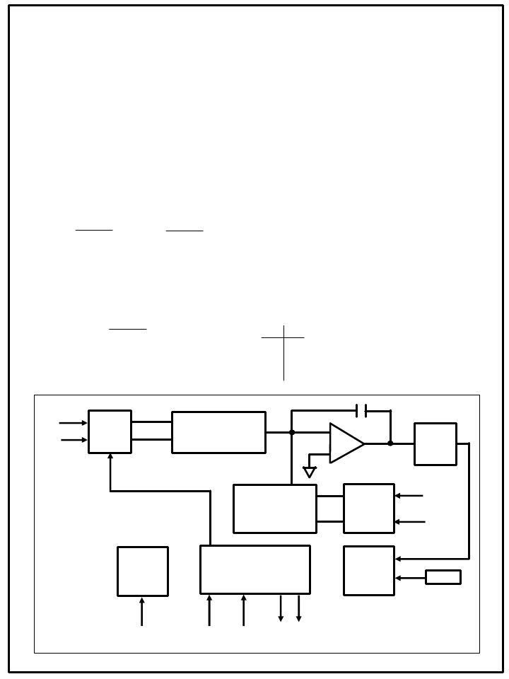
FIGURE 1. BLOCK DIAGRAM
Conversion in progress.
Conversion complete. MSB in output.
Middle byte in output register.
LSB in output. Ready for next conversion.
0 0
0 1
1 0
1 1
S
1
S
0
In the ADC100 block diagram (see Figure 1), V
and V
low
are the inputs. Both are buffered and fed
into a differential, voltage controlled, single output
current source. This current is added to the
reference current at the input of the op amp
integrator. The output of the integrator is fed into
a Schmitt trigger, which in turn, is fed into the
ADC's timing control circuitry. When the
integrator output actuates the Schmitt trigger, the
timing circuit changes the direction of the
reference current source and the integrator
begins integrating in the opposite direction. This
continues until the Schmitt trigger is actuated
again by the integrator and reverses the direction
of the reference current.
The equation for integration times are:
T
p
=
V X C
I
ref
+ I
inp
T
m
=
V X C
-I
ref
+ I
inp
Resolving these equations produces:
I
inp
= I
ref
T
p
- T
m
T
p
+ T
m
T
p =
Time Positive
T
m =
Time Negative
V = Voltage
C= Integration Capacitor Value
I
ref =
Reference Current
I
inp =
Input Current
ADC100DS REV. E MAR 00
Auto
Zero
Switch
Schmitt
Trigger
Bidirectional
Reference
Current Source
Current
Directional
Switch
Timing
Control
and
Counter
Microprocessor
Output
Buffer
Clock
Differential
Voltage Controlled
Current Source
V
hi
V
low
+15V
-15V
Auto
Zero
Convert
Status
Lines
Output Enable
Data
Output
相關(guān)PDF資料 |
PDF描述 |
|---|---|
| ADC100CA | Low-Voltage High-Speed Quadruple Differential Line Receiver 16-SOIC 0 to 70 |
| ADC100M | Low-Voltage High-Speed Quadruple Differential Line Receiver 16-SOIC 0 to 70 |
| ADC812 | Analog to Digital Converter 8 canali 12 bits |
| ADC82124 | 24 Ports 10/100 Fast Ethernet Switch Controller |
| ADEX-10L | Frequency Mixer Level 4 (LO Power +4 dBm) 10 to 1000 MHz |
相關(guān)代理商/技術(shù)參數(shù) |
參數(shù)描述 |
|---|---|
| ADC100CA | 制造商:未知廠家 制造商全稱:未知廠家 功能描述:Precision 22 Bit Integrating A/D Converter |
| ADC100M | 制造商:未知廠家 制造商全稱:未知廠家 功能描述:Precision 22 Bit Integrating A/D Converter |
| ADC101 | 制造商:MPSIND 制造商全稱:MPS Industries, Inc. 功能描述:1W, Miniature SIP, Single & Dual Output DC/DC Converters |
| ADC1010S | 制造商:PHILIPS 制造商全稱:NXP Semiconductors 功能描述:Single 10-bit ADC; 65 Msps, 80 Msps, 105 Msps or 125 Msps; CMOS or LVDS DDR digital outputs |
| ADC1010S065/DB,598 | 功能描述:數(shù)據(jù)轉(zhuǎn)換 IC 開發(fā)工具 ADC DEMO BOARD RoHS:否 制造商:Texas Instruments 產(chǎn)品:Demonstration Kits 類型:ADC 工具用于評估:ADS130E08 接口類型:SPI 工作電源電壓:- 6 V to + 6 V |
發(fā)布緊急采購,3分鐘左右您將得到回復(fù)。