- 您現在的位置:買賣IC網 > PDF目錄373976 > ADCMP562BRQ (ANALOG DEVICES INC) Dual High Speed PECL Comparators PDF資料下載
參數資料
| 型號: | ADCMP562BRQ |
| 廠商: | ANALOG DEVICES INC |
| 元件分類: | 運動控制電子 |
| 英文描述: | Dual High Speed PECL Comparators |
| 中文描述: | COMPARATOR, 10000 uV OFFSET-MAX, PDSO20 |
| 封裝: | MO-137AD, QSOP-20 |
| 文件頁數: | 6/16頁 |
| 文件大小: | 335K |
| 代理商: | ADCMP562BRQ |
ADCMP561/ADCMP562
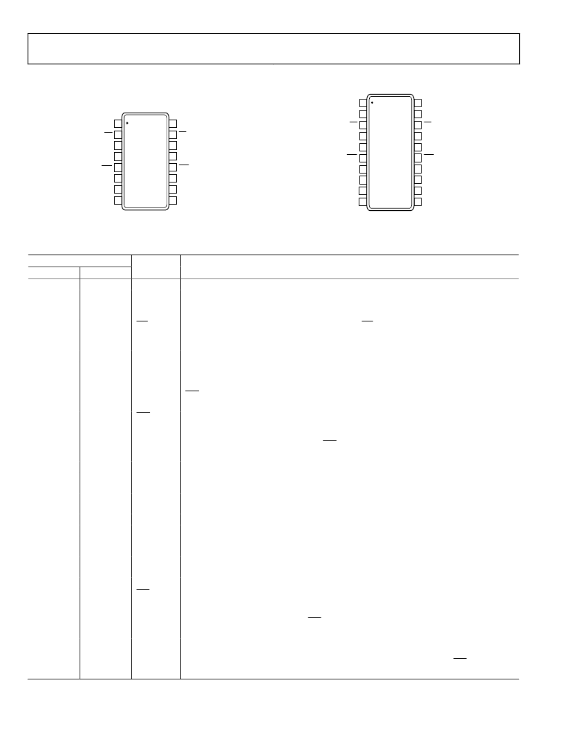
PIN CONFIGURATIONS AND FUNCTION DESCRIPTIONS
Rev. A | Page 6 of 16
0
ADCMP561
TOP VIEW
(Not to Scale)
1
2
3
4
5
6
7
8
16
15
14
13
12
11
10
9
–INA
+INA
QA
QA
V
DD
V
EE
LEA
LEA
–INB
+INB
QB
QB
GND
V
CC
LEB
LEB
0
ADCMP562
TOP VIEW
(Not to Scale)
1
2
3
4
5
6
7
8
9
10
20
19
18
17
16
15
14
13
12
11
–INA
QA
QA
V
DD
V
EE
LEA
LEA
V
DD
+INA
HYSA
–INB
QB
QB
GND
V
CC
LEB
LEB
V
DD
+INB
HYSB
Figure 4. ADCMP561 16-Lead QSOP Pin Configuration
Figure 5. ADCMP562 20-Lead QSOP Pin Configuration
Table 3. Pin Function Descriptions
Pin No.
ADCMP561
ADCMP562
1
1
2
Mnemonic
V
DD
QA
Function
Logic Supply Terminal.
One of two complementary outputs for Channel A. QA is logic high if the analog voltage at the
noninverting input is greater than the analog voltage at the inverting input (provided the
comparator is in compare mode). See the description of Pin LEA for more information.
One of two complementary outputs for Channel A. QA is logic low if the analog voltage at the
noninverting input is greater than the analog voltage at the inverting input (provided the
comparator is in compare mode). See the description of Pin LEA for more information.
Logic Supply Terminal.
One of two complementary inputs for Channel A Latch Enable. In compare mode (logic high),
the output tracks changes at the input of the comparator. In the latch mode (logic low), the
output reflects the input state just prior to the comparator’s being placed in the latch mode.
LEA must be driven in conjunction with LEA. If left unconnected, the comparator defaults to
compare mode.
One of two complementary inputs for Channel A Latch Enable. In compare mode (logic low),
the output tracks changes at the input of the comparator. In latch mode (logic high), the
output reflects the input state just prior to the comparator’s being placed in the latch mode.
LEA must be driven in conjunction with LEA. If left unconnected, the comparator defaults to
compare mode.
Negative Supply Terminal.
Inverting Analog Input of the Differential Input Stage for Channel A. The inverting A input must
be driven in conjunction with the noninverting A input.
Noninverting Analog Input of the Differential Input Stage for Channel A. The noninverting
A input must be driven in conjunction with the inverting A input.
Programmable Hysteresis Input.
Programmable Hysteresis Input.
Noninverting Analog Input of the Differential Input Stage for Channel B. The noninverting
B input must be driven in conjunction with the inverting B input.
Inverting Analog Input of the Differential Input Stage for Channel B. The inverting B input must
be driven in conjunction with the noninverting B input.
Positive Supply Terminal.
One of two complementary inputs for Channel B Latch Enable. In compare mode (logic low),
the output tracks changes at the input of the comparator. In latch mode (logic high), the
output reflects the input state just prior to placing the comparator in the latch mode. LEB
must be driven in conjunction with LEB. If left unconnected, the comparator defaults to
compare mode.
One of two complementary inputs for Channel B Latch Enable. In compare mode (logic high),
the output tracks changes at the input of the comparator. In latch mode (logic low), the output
reflects the input state just prior to placing the comparator in the latch mode. LEB must be
driven in conjunction with LEB. If left unconnected, the comparator defaults to compare mode.
2
3
QA
3
4
4
5
V
DD
LEA
5
6
LEA
6
7
7
8
V
EE
INA
8
9
+INA
9
10
11
12
HYSA
HYSB
+INB
10
13
INB
11
12
14
15
V
CC
LEB
13
16
LEB
相關PDF資料 |
PDF描述 |
|---|---|
| ADCMP563 | Dual High Speed ECL Comparators |
| ADCMP563BRQ | Dual High Speed ECL Comparators |
| ADCMP564 | Dual High Speed ECL Comparators |
| ADCMP564BRQ | Dual High Speed ECL Comparators |
| ADCMP566 | Dual Ultrafast Voltage Comparator |
相關代理商/技術參數 |
參數描述 |
|---|---|
| ADCMP562BRQZ | 功能描述:IC COMPARATOR PECL DUAL 20-QSOP RoHS:是 類別:集成電路 (IC) >> 線性 - 比較器 系列:- 標準包裝:1 系列:- 類型:通用 元件數:1 輸出類型:CMOS,開路集電極,TTL 電壓 - 電源,單路/雙路(±):2.7 V ~ 5.5 V 電壓 - 輸入偏移(最小值):7mV @ 5V 電流 - 輸入偏壓(最小值):0.25µA @ 5V 電流 - 輸出(標準):84mA @ 5V 電流 - 靜態(最大值):120µA CMRR, PSRR(標準):- 傳輸延遲(最大):600ns 磁滯:- 工作溫度:-40°C ~ 85°C 封裝/外殼:SC-74A,SOT-753 安裝類型:表面貼裝 包裝:剪切帶 (CT) 產品目錄頁面:1268 (CN2011-ZH PDF) 其它名稱:*LMV331M5*LMV331M5/NOPBLMV331M5CT |
| ADCMP562BRQZ-RL7 | 功能描述:IC COMPARATOR PECL DUAL 20QSOP RoHS:是 類別:集成電路 (IC) >> 線性 - 比較器 系列:- 產品培訓模塊:Lead (SnPb) Finish for COTS Obsolescence Mitigation Program 標準包裝:2,500 系列:- 類型:通用 元件數:1 輸出類型:CMOS,推挽式,滿擺幅,TTL 電壓 - 電源,單路/雙路(±):2.5 V ~ 5.5 V,±1.25 V ~ 2.75 V 電壓 - 輸入偏移(最小值):5mV @ 5.5V 電流 - 輸入偏壓(最小值):1pA @ 5.5V 電流 - 輸出(標準):- 電流 - 靜態(最大值):24µA CMRR, PSRR(標準):80dB CMRR,80dB PSRR 傳輸延遲(最大):450ns 磁滯:±3mV 工作溫度:-40°C ~ 85°C 封裝/外殼:6-WFBGA,CSPBGA 安裝類型:表面貼裝 包裝:管件 其它名稱:Q3554586 |
| ADCMP563 | 制造商:AD 制造商全稱:Analog Devices 功能描述:Dual High Speed ECL Comparators |
| ADCMP563_05 | 制造商:AD 制造商全稱:Analog Devices 功能描述:Dual, High Speed ECL Comparators |
| ADCMP563BCP-R2 | 制造商:Rochester Electronics LLC 功能描述: 制造商:Analog Devices 功能描述: |
發布緊急采購,3分鐘左右您將得到回復。