- 您現在的位置:買賣IC網 > PDF目錄373994 > ADL5501AKSZ-R2 (ANALOG DEVICES INC) 50 MHz to 4 GHz TruPwr Detector PDF資料下載
參數資料
| 型號: | ADL5501AKSZ-R2 |
| 廠商: | ANALOG DEVICES INC |
| 元件分類: | 電源管理 |
| 英文描述: | 50 MHz to 4 GHz TruPwr Detector |
| 中文描述: | 1-CHANNEL POWER SUPPLY SUPPORT CKT, PDSO6 |
| 封裝: | ROHS COMPLIANT, MO-203AB, SC-70, 6 PIN |
| 文件頁數: | 21/28頁 |
| 文件大小: | 1654K |
| 代理商: | ADL5501AKSZ-R2 |
第1頁第2頁第3頁第4頁第5頁第6頁第7頁第8頁第9頁第10頁第11頁第12頁第13頁第14頁第15頁第16頁第17頁第18頁第19頁第20頁當前第21頁第22頁第23頁第24頁第25頁第26頁第27頁第28頁
ADL5501
DEVICE CALIBRATION AND ERROR CALCULATION
Because slope and intercept vary from device to device, board-
level calibration must be performed to achieve high accuracy.
In general, calibration is performed by applying two input power
levels to the ADL5501 and measuring the corresponding output
voltages. The calibration points are generally chosen to be within
the linear operating range of the device. The best-fit line is char-
acterized by calculating the conversion gain (or slope) and intercept
using the following equations:
Gain
= (
V
RMS2
V
RMS1
)/(
V
IN2
V
IN1
)
Intercept
=
V
RMS1
(
Gain
×
V
IN1
)
where:
V
IN
is the rms input voltage to RFIN.
V
RMS
is the voltage output at VRMS.
Once gain and intercept are calculated, an equation can be
written that allows calculation of an (unknown) input power
based on the measured output voltage.
V
IN
= (
V
RMS
Intercept
)/
Gain
For an ideal (known) input power, the law conformance error of
the measured data can be calculated as
ERROR
(dB) =
20 × log [(
V
RMS, MEASURED
Intercept
)/(
Gain
×
V
IN, IDEAL
)] (6)
Figure 51 includes a plot of the error at 25°C, the temperature at
which the ADL5501 is calibrated. Note that the error is not zero.
This is because the ADL5501 does not perfectly follow the ideal
linear equation, even within its operating region. The error at
the calibration points is, however, equal to 0 by definition.
Rev. 0 | Page 21 of 28
(3)
(4)
(5)
3
–3
–2
–1
0
1
2
–25
–20
–15
–10
–5
0
5
+85°C
+25°C
–40°C
10
15
E
INPUT (dBm)
0
Figure 51. Error from Linear Reference vs. Input at 40°C, +25°C, and
+85°C vs. +25°C Linear Reference, Frequency 1900 MHz, Supply 5.0 V
Figure 51 also includes error plots for the output voltage at
40°C and +85°C. These error plots are calculated using the
gain and intercept at 25°C. This is consistent with calibration in
a mass-production environment where calibration at temperature
is not practical.
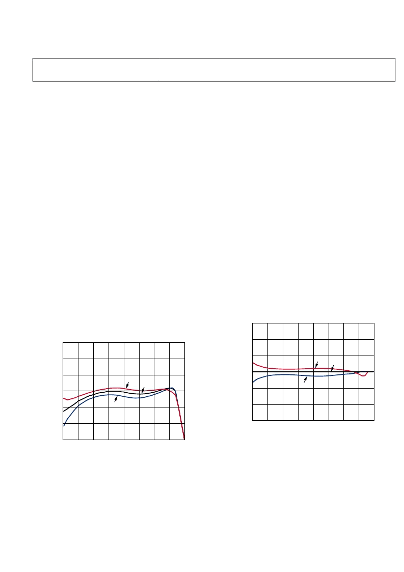
CALIBRATION FOR IMPROVED ACCURACY
Another way of presenting the error function of the ADL5501
is
shown in Figure 52. In this case, the dB error at hot and cold
temperatures is calculated with respect to the transfer function
at ambient. This is a key difference in comparison to the previous
plots. Up to now, the errors were calculated with respect to the
ideal linear transfer function at ambient. When this alternative
technique is used, the error at ambient becomes equal to 0 by
definition (see Figure 52).
This plot is a useful tool for estimating temperature drift at a
particular power level with respect to the (nonideal) response at
ambient. The linearity and dynamic range tend to be improved
artificially with this type of plot because the ADL5501 does not
perfectly follow the ideal linear equation (especially outside of
its linear operating range). Achieving this level of accuracy in
an end application requires calibration at multiple points in the
operating range of the device.
In some applications, very high accuracy is required at just one
power level or over a reduced input range. For example, in a
wireless transmitter, the accuracy of the high power amplifier
(HPA) is most critical at or close to full power. The ADL5501
offers a tight error distribution in the high input power range,
as shown in Figure 52. The high accuracy range, centered around
9 dBm at 1900 MHz, offers 7 dB of ±0.1 dB detection error over
temperature. Multiple point calibration at ambient temperature
in the reduced range offers precise power measurement with
near 0 dB error from 40°C to +85°C.
3
–3
–2
–1
0
1
2
–25
–20
–15
–10
–5
0
5
+85°C
+25°C
–40°C
10
15
E
INPUT (dBm)
0
Figure 52. Error from +25°C Output Voltage at 40°C, +25°C, and +85°C
After Ambient Normalization, Frequency 1900 MHz, Supply 5.0 V
The high accuracy range center varies over frequency. At
1900 MHz, the region is centered at approximately 9 dBm.
At higher frequencies, the high accuracy range is centered
at higher input powers (see Figure 13 through Figure 15 and
Figure 19 through Figure 21).
相關PDF資料 |
PDF描述 |
|---|---|
| ADL5501AKSZ-R7 | 50 MHz to 4 GHz TruPwr Detector |
| ADL5501-EVALZ | 50 MHz to 4 GHz TruPwr Detector |
| ADL5519 | 1 MHz to 10 GHz, 50 dB Dual Log Detector/Controller |
| ADL5519ACPZ-R2 | 1 MHz to 10 GHz, 50 dB Dual Log Detector/Controller |
| ADL5519ACPZ-R7 | 1 MHz to 10 GHz, 50 dB Dual Log Detector/Controller |
相關代理商/技術參數 |
參數描述 |
|---|---|
| ADL5501AKSZ-R21 | 制造商:AD 制造商全稱:Analog Devices 功能描述:50 MHz to 6 GHz TruPwr Detector |
| ADL5501AKSZ-R7 | 功能描述:IC DETECTOR RF/IF TRUPWR SC70-6 RoHS:是 類別:RF/IF 和 RFID >> RF 檢測器 系列:- 產品變化通告:Product Discontinuation 15/May/2006 標準包裝:3,000 系列:- 頻率:100MHz ~ 2GHz RF 型:手機,GSM,DCS,PCS 輸入范圍:- 精確度:- 電源電壓:2.7 V ~ 5.5 V 電流 - 電源:300µA 包裝:帶卷 (TR) 封裝/外殼:SC-74,SOT-457 其它名稱:NCS5000SNT1GOS |
| ADL5501AKSZ-R71 | 制造商:AD 制造商全稱:Analog Devices 功能描述:50 MHz to 6 GHz TruPwr Detector |
| ADL5501-EVALZ | 制造商:Analog Devices 功能描述:EVAL KIT FOR 50 MHZ TO 4 GHZ TRUPWR DETECTOR - Bulk |
| ADL5501-EVALZ1 | 制造商:AD 制造商全稱:Analog Devices 功能描述:50 MHz to 6 GHz TruPwr Detector |
發布緊急采購,3分鐘左右您將得到回復。