- 您現在的位置:買賣IC網 > PDF目錄374009 > ADM705 (Analog Devices, Inc.) Low Cost uP Supervisory Circuits PDF資料下載
參數資料
| 型號: | ADM705 |
| 廠商: | Analog Devices, Inc. |
| 英文描述: | Low Cost uP Supervisory Circuits |
| 中文描述: | 低成本的監控電路 |
| 文件頁數: | 3/8頁 |
| 文件大小: | 143K |
| 代理商: | ADM705 |
ADM705–ADM708
REV. B
–3–
PIN FUNCTION DESCRIPTION
ADM705
ADM706
DIP, SOIC
Pin No.
ADM707
ADM708
Mnemonic
DIP, SPOC
MicroSOIC
Function
MR
1
1
3
Manual Reset Input. When taken below 0.8 V, a RESET is gener-
ated.
MR
can be driven from TTL, CMOS logic or from a manual
reset switch as it is internally debounced. An internal 250
μ
A pull-up
current holds the input high when floating.
5 V Power Supply Input.
0 V. Ground reference for all signals.
Power-Fail Input. PFI is the noninverting input to the Power-Fail
Comparator. When PFI is less than 1.25 V,
PFO
goes low. If unused,
PFI should be connected to GND or V
CC
.
Power-Fail Output.
PFO
is the output from the Power-Fail Compara-
tor. It goes low when PFI is less than 1.25 V.
Watchdog Input. WDI is a three-level input. If WDI remains either
high or low for longer than the watchdog timeout period, the watch-
dog output
WDO
goes low. The timer resets with each transition at
the WDI input.
Either a high-to-low or a low-to-high transition will clear the counter.
The internal timer is also cleared whenever reset is asserted. The
watchdog timer is disabled when WDI is left floating or connected to
a three-state buffer.
No Connect.
Logic Output.
RESET
goes low for 200 ms when triggered. It can be
triggered either by V
CC
being below the reset threshold or by a low
signal on the manual reset (
MR
) input.
RESET
will remain low
whenever V
CC
is below the reset threshold (4.65 V in ADM705, 4.4 V
in ADM706). It remains low for 200 ms after V
CC
goes above the
reset threshold or
MR
goes from low to high. A watchdog timeout
will not trigger
RESET
unless
WDO
is connected to
MR
.
Logic Output. The Watchdog Output,
WDO
, goes low if the internal
watchdog timer times out as a result of inactivity on the WDI input. It
remains low until the watchdog timer is cleared.
WDO
also goes low
during low line conditions. Whenever V
CC
is below the reset threshold,
WDO
remains low. As soon as V
CC
goes above the reset threshold,
WDO
goes high immediately.
Logic Output. RESET is an active high output suitable for systems
that use active high RESET logic. It is the inverse of
RESET
.
V
CC
GND
PFI
2
3
4
2
3
4
4
5
6
PFO
5
5
7
WDI
6
N/A
N/A
NC
RESET
N/A
7
6
7
8
1
WDO
8
N/A
N/A
RESET
N/A
8
2
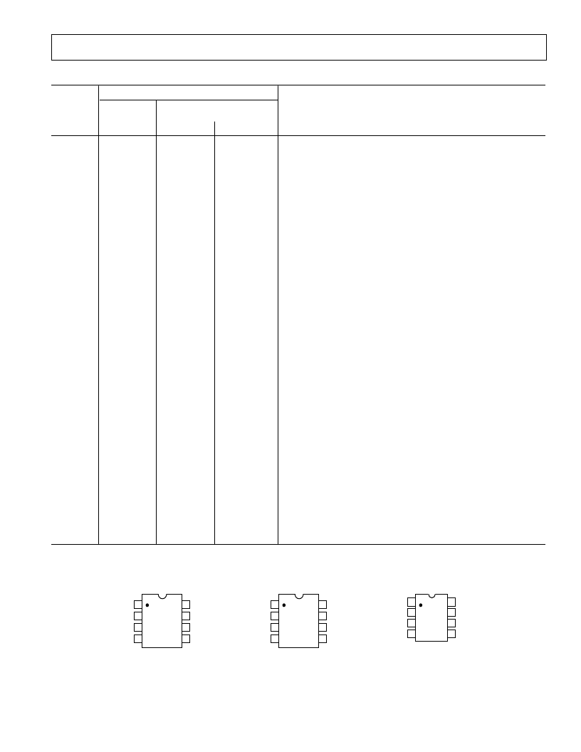
PIN CONFIGURATION
DIP, SOIC DIP, SOIC MicroSOIC
1
2
3
4
8
7
6
5
(TOP VIEW
NC = NO CONNECT
ADM707/
ADM708
RESET
GND
PFI
PFO
NC
RESET
MR
V
CC
8
7
6
5
1
2
3
4
(TOP VIEW
ADM705/
ADM706
MR
PFO
WDI
RESET
WDO
V
CC
GND
PFI
8
7
6
5
1
2
3
4
(TOP VIEW
NC = NO CONNECT
ADM707/
ADM708
MR
PFO
NC
RESET
RESET
V
CC
GND
PFI
相關PDF資料 |
PDF描述 |
|---|---|
| ADM705AN | Low Cost uP Supervisory Circuits |
| ADM705AR | Low Cost uP Supervisory Circuits |
| ADM706AN | Low Cost uP Supervisory Circuits |
| ADM706AR | Low Cost uP Supervisory Circuits |
| ADM706P | +3 V, Voltage Monitoring uP Supervisory Circuits |
相關代理商/技術參數 |
參數描述 |
|---|---|
| ADM705_08 | 制造商:AD 制造商全稱:Analog Devices 功能描述:Supervisory Circuits |
| ADM705-ADM708 | 制造商:AD 制造商全稱:Analog Devices 功能描述:Low Cost uP Supervisory Circuits |
| ADM705AN | 功能描述:IC SUPERVISOR MPU 4.65 WD 8DIP RoHS:否 類別:集成電路 (IC) >> PMIC - 監控器 系列:- 標準包裝:1 系列:- 類型:簡單復位/加電復位 監視電壓數目:1 輸出:開路漏極或開路集電極 復位:高有效 復位超時:- 電壓 - 閥值:1.8V 工作溫度:-40°C ~ 125°C 安裝類型:表面貼裝 封裝/外殼:6-TSOP(0.059",1.50mm 寬)5 引線 供應商設備封裝:5-TSOP 包裝:剪切帶 (CT) 其它名稱:NCP301HSN18T1GOSCT |
| ADM705ANZ | 功能描述:IC SUPERVISOR MPU 4.65 WD 8-DIP RoHS:是 類別:集成電路 (IC) >> PMIC - 監控器 系列:- 標準包裝:100 系列:- 類型:簡單復位/加電復位 監視電壓數目:1 輸出:開路漏極,開路漏極 復位:高有效/低有效 復位超時:最小為 250 ms 電壓 - 閥值:4.37V,4.62V 工作溫度:0°C ~ 70°C 安裝類型:表面貼裝 封裝/外殼:8-SOIC(0.154",3.90mm 寬) 供應商設備封裝:8-SOIC 包裝:管件 產品目錄頁面:1337 (CN2011-ZH PDF) |
| ADM705ANZ | 制造商:Analog Devices 功能描述:IC RESET GENERATOR |
發布緊急采購,3分鐘左右您將得到回復。