- 您現在的位置:買賣IC網 > PDF目錄374016 > ADM8845 (Analog Devices, Inc.) Charge Pump Driver for LCD White LED Backlights PDF資料下載
參數資料
| 型號: | ADM8845 |
| 廠商: | Analog Devices, Inc. |
| 英文描述: | Charge Pump Driver for LCD White LED Backlights |
| 中文描述: | 電荷泵驅動器的液晶顯示白色LED背光源 |
| 文件頁數: | 5/18頁 |
| 文件大小: | 341K |
| 代理商: | ADM8845 |
Preliminary Technical Data
ADM8845
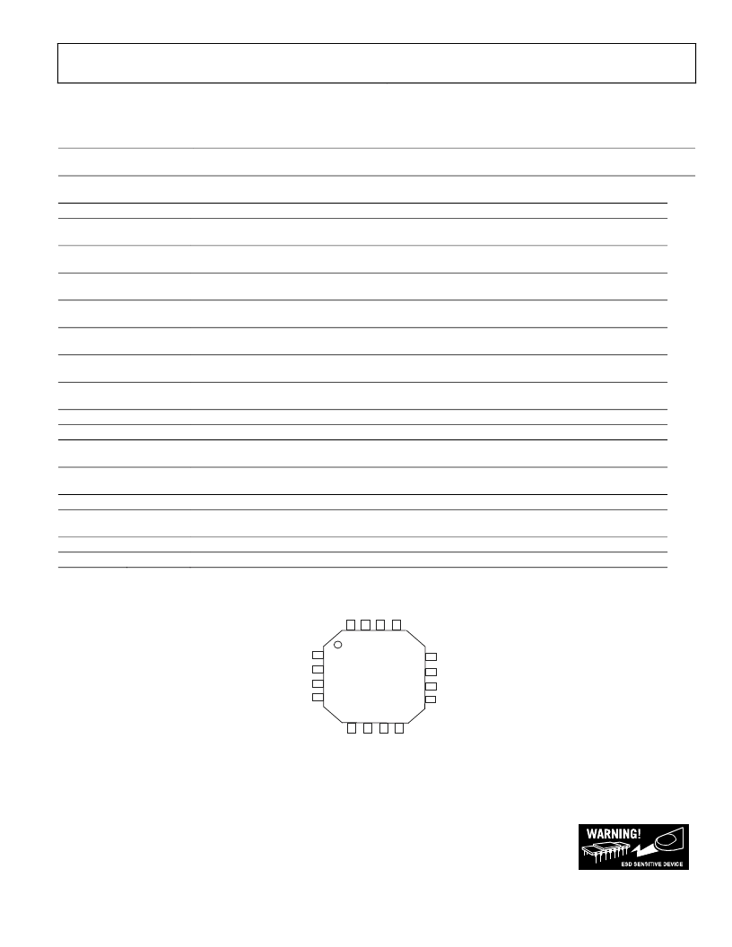
PIN CONFIGURATION AND FUNCTION DESCRIPTION
Table 3.
Pin
ADM8845
Mnemonic
Function
Charge Pump Output. A 2.2μF capacitor to ground is required on this pin. Connect Vout to the anodes
of all the LEDs.
2
C2+
Flying Capacitor 2 Positive Connection
Bias current set input. The current flowing through the R
SET
resistor I
SET
is gained up by 120 to give the
I
LED
curent. Connect a resistor R
SET
to GND to set the bias current as V
SET
/R
SET
. (Note: Vset = 1.18V)
LED1 Cathode connection and Charge Pump Feedback. The current flowing in LED1 is 120 times the
current flowing through R
SET
, I
SET
.
LED2 Cathode connection and Charge Pump Feedback. The current flowing in LED2 is 120 times the
current flowing through R
SET
, I
SET
. When using fewer than six LEDs this pin can be left unconnected.
LED3 Cathode connection and Charge Pump Feedback. The current flowing in LED3 is 120 times the
current flowing through R
SET
, I
SET
. When using fewer than six LEDs this pin can be left unconnected.
LED4 Cathode connection and Charge Pump Feedback. The current flowing in LED4 is 120 times the
current flowing through R
SET
, I
SET
. When using fewer than six LEDs this pin can be left unconnected.
LED5 Cathode connection and Charge Pump Feedback. The current flowing in LED5 is 120 times the
current flowing through R
SET
, I
SET
. When using fewer than six LEDs this pin can be left unconnected.
LED6 Cathode connection and Charge Pump Feedback. The current flowing in LED6 is 120 times the
current flowing through R
SET
, I
SET
. When using fewer than six LEDs this pin can be left unconnected.
10
G N D
Device Ground Pin.
11
C2
Flying Capacitor 2 Negative Connection.
Digital Input. 3 V CMOS Logic. Used with CTRL1 to control the shutdown operation of the main and sub
LEDs.
Digital Input. 3 V CMOS Logic. Used with CTRL2 to control the shutdown operation of the main and sub
LEDs.
14
C1
Flying Capacitor 1 Negative Connection.
Positive Supply Voltage Input. Connect this pin to a 2.6 V to 5.5 V supply with a 4.7μF decoupling
capacitor.
16
C1+
Flying Capacitor 1 Positive Connection.
-
EP
Expose Paddle. Connect the exposed paddle to GND.
Rev. PrJ 06/04| Page 5 of 18
1
VOUT
3
I
SET
4
FB1
5
FB2
6
FB3
7
FB4
8
FB5
9
FB6
12
CTRL2
13
CTRL1
15
Vcc
10
11
12
9
1
2
3
4
5
6
7
8
13
14
15
ADM8845
TOP VIEW
(NOT TO SCALE)
16
Figure 3. ADM8845 Pin Configuration
ESD (electrostatic discharge) sensitive device. Electrostatic charges as high as 4000 V readily accumulate on the
human body and test equipment and can discharge without detection. Although this product features
proprietary ESD protection circuitry, permanent damage may occur on devices subjected to high energy
electrostatic discharges. Therefore, proper ESD precautions are recommended to avoid performance
degradation or loss of functionality.
相關PDF資料 |
PDF描述 |
|---|---|
| ADM8845ACP | Charge Pump Driver for LCD White LED Backlights |
| ADM8845ACP-REEL7 | Charge Pump Driver for LCD White LED Backlights |
| ADM8845ACPZ | Charge Pump Driver for LCD White LED Backlights |
| ADM8845ACPZ-REEL7 | 20-21 (9 Contact) Pin Insert; For Use With:Amphenol MIL-C-5015 97 Series Circular Connectors; No. of Contacts:9; Gender:Male; Operating Voltage:700V |
| ADM9240 | Low Cost Microprocessor System Hardware Monitor |
相關代理商/技術參數 |
參數描述 |
|---|---|
| ADM8845ACP | 制造商:Analog Devices 功能描述:CHG PUMP STPUP 30MA 16LFCSP - Bulk |
| ADM8845ACP-REEL | 制造商:Analog Devices 功能描述:Charge Pump STPUP 30mA 16-Pin LFCSP EP T/R |
| ADM8845ACP-REEL7 | 制造商:Analog Devices 功能描述:Charge Pump STPUP 30mA 16-Pin LFCSP EP T/R |
| ADM8845ACPZ | 制造商:AD 制造商全稱:Analog Devices 功能描述:Charge Pump Driver for LCD White LED Backlights |
| ADM8845ACPZ-REEL | 功能描述:IC LED DRVR WHITE BCKLGT 16LFCSP RoHS:是 類別:集成電路 (IC) >> PMIC - LED 驅動器 系列:- 標準包裝:6,000 系列:- 恒定電流:- 恒定電壓:- 拓撲:開路漏極,PWM 輸出數:4 內部驅動器:是 類型 - 主要:LED 閃爍器 類型 - 次要:- 頻率:400kHz 電源電壓:2.3 V ~ 5.5 V 輸出電壓:- 安裝類型:表面貼裝 封裝/外殼:8-VFDFN 裸露焊盤 供應商設備封裝:8-HVSON 包裝:帶卷 (TR) 工作溫度:-40°C ~ 85°C 其它名稱:935286881118PCA9553TK/02-TPCA9553TK/02-T-ND |
發布緊急采購,3分鐘左右您將得到回復。