- 您現在的位置:買賣IC網 > PDF目錄92909 > ADP-2-10W-75+ (MINI-CIRCUITS) 5 MHz - 1000 MHz RF/MICROWAVE COMBINER, 1.1 dB INSERTION LOSS PDF資料下載
參數資料
| 型號: | ADP-2-10W-75+ |
| 廠商: | MINI-CIRCUITS |
| 元件分類: | 分路器/合路器 |
| 英文描述: | 5 MHz - 1000 MHz RF/MICROWAVE COMBINER, 1.1 dB INSERTION LOSS |
| 封裝: | ROHS COMPLIANT, CASE CD636, 6 PIN |
| 文件頁數: | 1/1頁 |
| 文件大小: | 284K |
| 代理商: | ADP-2-10W-75+ |
FREQ.
RANGE
(MHz)
ISOLATION
(dB)
INSERTION LOSS (dB)
ABOVE 3.0 dB
PHASE
UNBALANCE
(Degrees)
AMPLITUDE
UNBALANCE
(dB)
f
L-fU
L
M
U
L
M
U
L
M
U
L
M
U
Typ. Min Typ. Min Typ. Min Typ. Max. Typ. Max. Typ. Max.
Max.
5-1000
24
14
23
18
24
18
0.2
0.6
0.3
0.9
0.5
1.1
1.0
3.0
5.0
0.1
0.2
0.3
L = low range [f
L to 10 fL]
M = mid range [10 f
L to fU/2]
U = upper range [f
U/2 to fU]
ISO 9001 ISO 14001 AS 9100 CERTIFIED
Mini-Circuits
P.O. Box 350166, Brooklyn, New York 11235-0003 (718) 934-4500 Fax (718) 332-4661 The Design Engineers Search Engine
Provides ACTUAL Data Instantly at
Notes: 1. Performance and quality attributes and conditions not expressly stated in this specification sheet are intended to be excluded and do not form a part of this specification sheet. 2. Electrical specifications
and performance data contained herein are based on Mini-Circuit’s applicable established test performance criteria and measurement instructions. 3. The parts covered by this specification sheet are subject to
Mini-Circuits standard limited warranty and terms and conditions (collectively, “Standard Terms”); Purchasers of this part are entitled to the rights and benefits contained therein. For a full statement of the Standard
Terms and the exclusive rights and remedies thereunder, please visit Mini-Circuits’ website at www.minicircuits.com/MCLStore/terms.jsp.
For detailed performance specs
& shopping online see web site
minicircuits.com
IF/RF MICROWAVE COMPONENTS
A
B
C
D
E
F
G
.272
.310
.220
.100
.162
.055
.100
6.91
7.87
5.59
2.54
4.11
1.40
2.54
H
J
K
L
wt
.030
.026
.065
.300
grams
0.76
0.66
1.65
7.62
0.25
ADP-2-10W-75+
ADP-2-10W-75
2 Way-0°
75
5 to 1000 MHz
Power Splitter/Combiner
Surface Mount
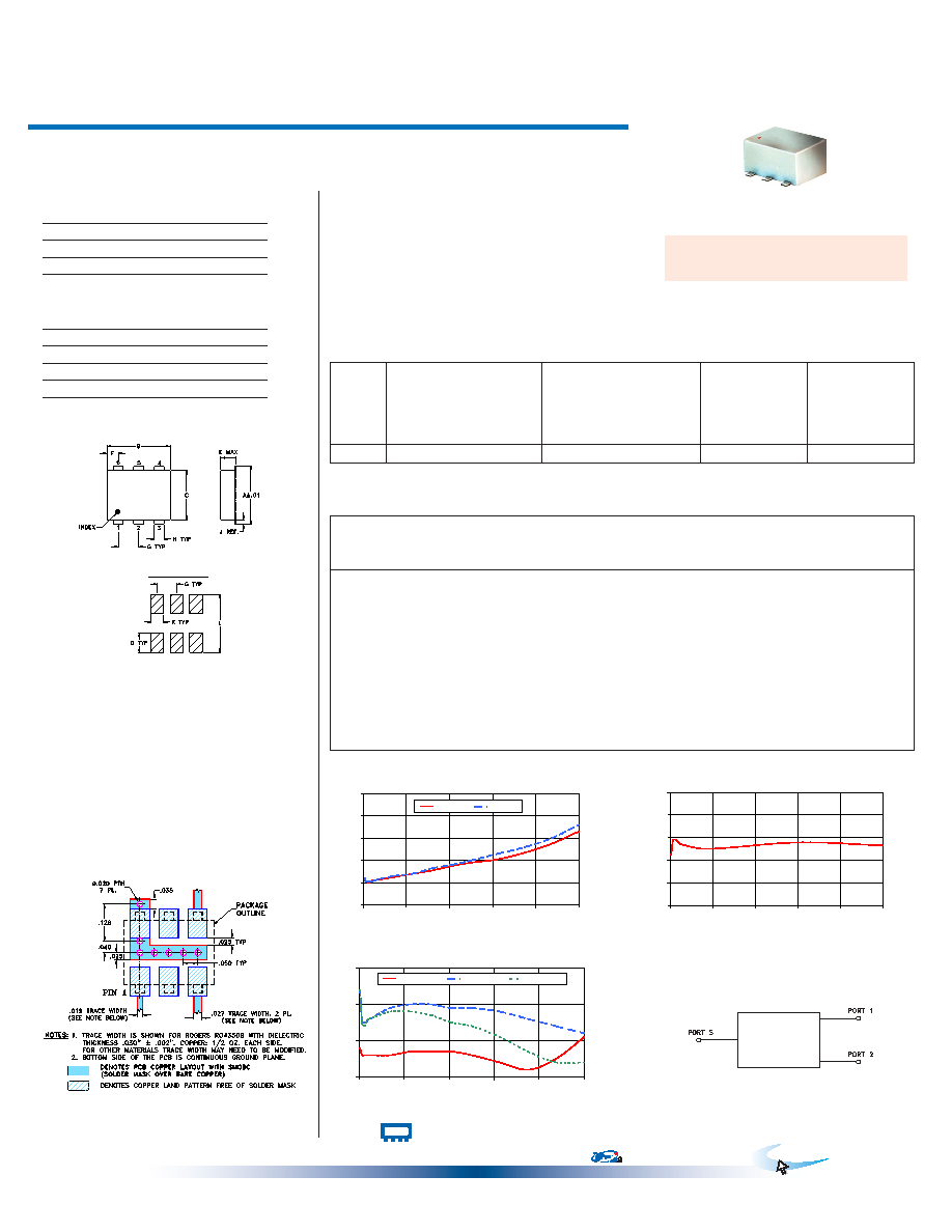
Typical Performance Data
Electrical Specifications
Maximum Ratings
Operating Temperature
-40°C to 85°C
Storage Temperature
-55°C to 100°C
Power Input (as a splitter)
0.5W max.
Internal Dissipation
0.125W max.
Outline Drawing
Outline Dimensions (
)
inch
mm
electrical schematic
PCB Land Pattern
Suggested Layout,
Tolerance to be within ±.002
REV. C
M127604
ADP-2-10W-75
DY/TD/CP/AM
100528
CASE STYLE: CD636
PRICE: $12.95 ea. QTY. (10-49)
Frequency
(MHz)
Total Loss1
(dB)
Amplitude
Unbalance
(dB)
Isolation
(dB)
Phase
Unbalance
(deg.)
VSWR
S
VSWR
1
VSWR
2
S-1
S-2
Features
wideband, 5 to 1000 MHz
low insertion loss, 0.3 dB typ.
aqueous washable
protected under U.S. Patent 6,133,525
Applications
cellular
VHF/UHF
communication systems
CATV
Pin Connections
SUM PORT
1
PORT 1
3
PORT 2
4
GROUND
6
NOT USED
2,5
Demo Board MCL P/N: TB-243
Suggested PCB Layout (PL-141)
ADP-2-10W-75
TOTAL LOSS
3.0
3.2
3.4
3.6
3.8
4.0
0
200
400
600
800
1000
FREQUENCY (MHz)
TO
TA
L
LO
S
(d
B
)
S-1(dB)
S-2(dB)
ADP-2-10W-75
ISOLATION
10
15
20
25
30
35
0
200
400
600
800
1000
FREQUENCY(MHz)
IS
O
LA
TI
O
N
(d
B
)
ADP-2-10W-75
VSWR
1.0
1.1
1.2
1.3
0
200
400
600
800
1000
FREQUENCY (MHz)
V
S
W
R
#S-VSWR
#1-VSWR
#2-VSWR
+ RoHS compliant in accordance
with EU Directive (2002/95/EC)
The +Suffix identifies RoHS Compliance. See our web site
for RoHS Compliance methodologies and qualifications.
5.00
3.23
3.24
0.01
21.20
0.03
1.08
1.24
14.00
3.21
0.00
24.46
0.01
1.06
1.15
23.00
3.20
3.21
0.01
24.61
0.06
1.06
1.15
1.14
32.00
3.21
0.00
24.23
0.07
1.06
1.15
41.00
3.22
3.21
0.00
23.86
0.16
1.06
1.16
50.00
3.22
0.01
23.55
0.12
1.06
1.16
140.00
3.25
3.26
0.00
22.59
0.38
1.06
1.19
1.18
230.00
3.28
0.00
22.63
0.64
1.07
1.20
1.18
320.00
3.31
3.33
0.02
22.95
0.87
1.07
1.20
1.17
410.00
3.35
3.36
0.01
23.35
1.06
1.07
1.19
1.15
500.00
3.38
3.40
0.02
23.72
1.27
1.06
1.19
1.14
625.00
3.41
3.46
0.05
23.96
1.61
1.04
1.18
1.11
750.00
3.47
3.52
0.05
23.86
1.85
1.02
1.16
1.07
875.00
3.55
3.60
0.06
23.54
2.10
1.05
1.14
1.04
1000.00
3.66
3.72
0.06
23.25
2.21
1.11
1.12
1.04
Permanent damage may occur if any of these limits are
exceeded.
1. Total Loss = Insertion Loss + 3dB splitter loss.
相關PDF資料 |
PDF描述 |
|---|---|
| ADP-2-20-75 | 5 MHz - 2000 MHz RF/MICROWAVE COMBINER, 1.4 dB INSERTION LOSS |
| ADP-2-20-75+ | 5 MHz - 2000 MHz RF/MICROWAVE COMBINER, 1.4 dB INSERTION LOSS |
| ADP-2-20 | 20 MHz - 2000 MHz RF/MICROWAVE COMBINER, 1.5 dB INSERTION LOSS |
| ADP-2-4 | 10 MHz - 1000 MHz RF/MICROWAVE COMBINER, 1.5 dB INSERTION LOSS |
| ADP-2-9+ | 200 MHz - 900 MHz RF/MICROWAVE COMBINER, 0.8 dB INSERTION LOSS |
相關代理商/技術參數 |
參數描述 |
|---|---|
| ADP2114 | 制造商:AD 制造商全稱:Analog Devices 功能描述:Configurable, Dual 2 A/Single 4 A, Synchronous Step-Down DC-to-DC Regulator |
| ADP2114-2PH-EVALZ | 功能描述:BOARD EVALUATION 1.2V 4A 1.2MHZ RoHS:是 類別:編程器,開發系統 >> 評估板 - DC/DC 與 AC/DC(離線)SMPS 系列:- 標準包裝:1 系列:- 主要目的:DC/DC,步降 輸出及類型:1,非隔離 功率 - 輸出:- 輸出電壓:3.3V 電流 - 輸出:3A 輸入電壓:4.5 V ~ 28 V 穩壓器拓撲結構:降壓 頻率 - 開關:250kHz 板類型:完全填充 已供物品:板 已用 IC / 零件:L7981 其它名稱:497-12113STEVAL-ISA094V1-ND |
| ADP2114ACPZ-R2 | 功能描述:直流/直流開關調節器 Dual-Step Down Converter w/ 2A x 2output RoHS:否 制造商:International Rectifier 最大輸入電壓:21 V 開關頻率:1.5 MHz 輸出電壓:0.5 V to 0.86 V 輸出電流:4 A 輸出端數量: 最大工作溫度: 安裝風格:SMD/SMT 封裝 / 箱體:PQFN 4 x 5 |
| ADP2114ACPZ-R7 | 功能描述:IC REG BUCK SYNC ADJ 32LFCSP RoHS:是 類別:集成電路 (IC) >> PMIC - 穩壓器 - DC DC 開關穩壓器 系列:- 產品培訓模塊:Lead (SnPb) Finish for COTS Obsolescence Mitigation Program 標準包裝:50 系列:- 類型:升壓(升壓) 輸出類型:兩者兼有 輸出數:1 輸出電壓:5V,2 V ~ 16.5 V 輸入電壓:2 V ~ 16.5 V PWM 型:- 頻率 - 開關:45kHz 電流 - 輸出:50mA 同步整流器:無 工作溫度:0°C ~ 70°C 安裝類型:通孔 封裝/外殼:8-DIP(0.300",7.62mm) 包裝:管件 供應商設備封裝:8-PDIP |
| ADP2114ACPZ-R7 | 制造商:Analog Devices 功能描述:DC/DC Converter IC 制造商:Analog Devices 功能描述:IC, SYNC STEP-DOWN DC/DC REG, LFCSP-32 |
發布緊急采購,3分鐘左右您將得到回復。