- 您現(xiàn)在的位置:買賣IC網(wǎng) > PDF目錄374019 > ADP3000AR-3.3 (ANALOG DEVICES INC) Voltage-Mode SMPS Controller PDF資料下載
參數(shù)資料
| 型號: | ADP3000AR-3.3 |
| 廠商: | ANALOG DEVICES INC |
| 元件分類: | 穩(wěn)壓器 |
| 英文描述: | Voltage-Mode SMPS Controller |
| 中文描述: | SWITCHING REGULATOR, 400 kHz SWITCHING FREQ-MAX, PDSO8 |
| 封裝: | MS-012-AA, SOIC-8 |
| 文件頁數(shù): | 1/12頁 |
| 文件大小: | 342K |
| 代理商: | ADP3000AR-3.3 |
REV. 0
Information furnished by Analog Devices is believed to be accurate and
reliable. However, no responsibility is assumed by Analog Devices for its
use, nor for any infringements of patents or other rights of third parties
which may result from its use. No license is granted by implication or
otherwise under any patent or patent rights of Analog Devices.
a
ADP3000
One Technology Way, P.O. Box 9106, Norwood, MA 02062-9106, U.S.A.
Tel: 617/329-4700
World Wide Web Site: http://www.analog.com
Fax: 617/326-8703
Analog Devices, Inc., 1997
Micropower Step-Up/Step-Down
Fixed 3.3 V, 5 V, 12 V and Adjustable
High Frequency Switching Regulator
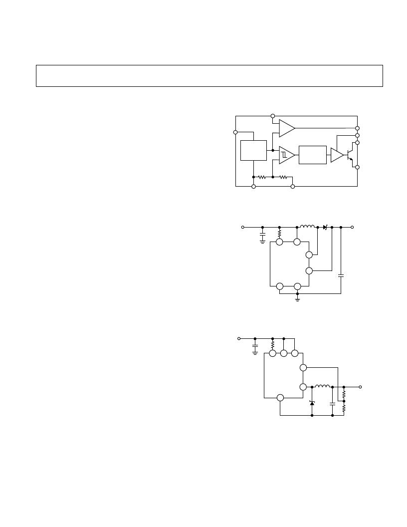
FUNCTIONAL BLOCK DIAGRAM
COMPARATOR
GAIN BLOCK/
ERROR AMP
400kHz
OSCILLATOR
DRIVER
A1
1.245V
REFERENCE
R1
R2
ADP3000
SET
V
IN
GND
SENSE
A0
I
LIM
SW1
SW2
FEATURES
Operates at Supply Voltages from 2 V to 30 V
Works in Step-Up or Step-Down Mode
Very Few External Components Required
High Frequency Operation Up to 400 kHz
Low Battery Detector on Chip
User Adjustable Current Limit
Fixed and Adjustable Output Voltage
8-Pin DIP and SO-8 Package
Small Inductors and Capacitors
APPLICATIONS
Notebook, Palmtop Computers
Cellular Telephones
Hard Disk Drives
Portable Instruments
Pagers
GENERAL DESCRIPTION
The ADP3000 is a versatile step-up/step-down switching
regulator that operates from an input supply voltage of 2 V to
12 V in step-up mode and up to 30 V in step-down mode.
The ADP3000 operates in Pulse Frequency Mode (PFM) and
consumes only 500
μ
A, making it highly suitable for applica-
tions that require low quiescent current.
The ADP3000 can deliver an output current of 100 mA at
3 V from a 5 V input in step-down configuration and 180 mA at
3.3 V from a 2 V input in step-up configuration.
The auxiliary gain amplifier can be used as a low battery detector,
linear regulator undervoltage lockout or error amplifier.
The ADP3000 operates at 400 kHz switching frequency. This
allows the use of small external components (inductors and
capacitors), making the device very suitable for space constrained
designs.
ADP3000-3.3V
1
2
3
8
4
5
I
LIM
V
IN
SW1
FB
(SENSE)
SW2
GND
+
100μF
10V
120
6.8μH
IN5817
C1
100μF
10V
V
IN
2V–3.2V
3.3V @
180mA
C1, C2: AVX TPS D107 M010R0100
L1: SUMIDA CD43-6R8
Figure 1. Typical Application
ADP3000
1
2
3
8
4
5
I
LIM
V
IN
SW1
FB
SW2
GND
C1
100μF
10V
R
LIM
120
L1
10μH
V
IN
5V–6V
C1, C2: AVX TPS D107 M010R0100
L1: SUMIDA CD43-100
+
D1
1N5818
CL
100μF
10V
R2
R1
110k
1%
V
OUT
3V
100mA
Figure 2. Step-Down Mode Operation
相關(guān)PDF資料 |
PDF描述 |
|---|---|
| ADP3000AN-12 | Isolated Flyback Switching Regulator with 9V Output |
| ADP3000AN-33 | Isolated Flyback Switching Regulator with 9V Output |
| ADP3000AN-5 | Isolated Flyback Switching Regulator with 9V Output |
| ADP3000AR | Isolated Flyback Switching Regulator with 9V Output |
| ADP3000AR-5 | Isolated Flyback Switching Regulator with 9V Output |
相關(guān)代理商/技術(shù)參數(shù) |
參數(shù)描述 |
|---|---|
| ADP3000AR-5 | 制造商:Analog Devices 功能描述:Conv DC-DC Single Non-Inv/Inv/Step Up/Step Down 2V to 30V 8-Pin SOIC N |
| ADP3000AR-5-REEL | 制造商:Analog Devices 功能描述: |
| ADP3000AR-REEL | 制造商:Rochester Electronics LLC 功能描述:- Tape and Reel |
| ADP3000ARU | 制造商:AD 制造商全稱:Analog Devices 功能描述:Micropower Step-Up/Step-Down Fixed 3.3 V, 5 V, 12 V, Adjustable High Frequency Switching Regulator |
| ADP3000ARU-REEL | 制造商:Rochester Electronics LLC 功能描述:MCROPWR STPUP/DWN H. FRQ. - Tape and Reel |
發(fā)布緊急采購,3分鐘左右您將得到回復(fù)。