- 您現在的位置:買賣IC網 > PDF目錄92910 > ADQ-90 (MINI-CIRCUITS) 55 MHz - 90 MHz RF/MICROWAVE COMBINER, 0.7 dB INSERTION LOSS PDF資料下載
參數資料
| 型號: | ADQ-90 |
| 廠商: | MINI-CIRCUITS |
| 元件分類: | 分路器/合路器 |
| 英文描述: | 55 MHz - 90 MHz RF/MICROWAVE COMBINER, 0.7 dB INSERTION LOSS |
| 封裝: | CASE CJ725, 8 PIN |
| 文件頁數: | 1/1頁 |
| 文件大小: | 310K |
| 代理商: | ADQ-90 |
ISO 9001 ISO 14001 AS 9100 CERTIFIED
Mini-Circuits
P.O. Box 350166, Brooklyn, New York 11235-0003 (718) 934-4500 Fax (718) 332-4661 The Design Engineers Search Engine
Provides ACTUAL Data Instantly at
Notes: 1. Performance and quality attributes and conditions not expressly stated in this specification sheet are intended to be excluded and do not form a part of this specification sheet. 2. Electrical specifications
and performance data contained herein are based on Mini-Circuit’s applicable established test performance criteria and measurement instructions. 3. The parts covered by this specification sheet are subject to
Mini-Circuits standard limited warranty and terms and conditions (collectively, “Standard Terms”); Purchasers of this part are entitled to the rights and benefits contained therein. For a full statement of the Standard
Terms and the exclusive rights and remedies thereunder, please visit Mini-Circuits’ website at www.minicircuits.com/MCLStore/terms.jsp.
For detailed performance specs
& shopping online see web site
minicircuits.com
IF/RF MICROWAVE COMPONENTS
A
B
C
D
E
F
G
.345
.400
.385
.435
.310
.215
.100
8.76 10.16
9.78 11.05
7.87
5.46
2.54
H
J
K
L
M
N
P
wt
.015
.025
.035
.075
.120
.060
.420 grams
0.38
0.64
0.89
1.91
3.05
1.52 10.67
0.45
Frequency
(MHz)
Total Loss1
(dB)
Amplitude
Unbalance
(dB)
Isolation
(dB)
Phase
Unbalance
(deg.)
VSWR
S
VSWR
1
VSWR
2
S-1
S-2
ADQ-90
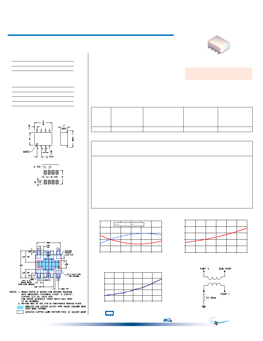
TOTAL LOSS
2.4
2.8
3.2
3.6
4.0
4.4
54
60
66
72
78
84
90
FREQUENCY (MHz)
TOTAL
LOSS
(dB)
S-1(dB)
S-2(dB)
Typical Performance Data
Electrical Specifications
Maximum Ratings
Pin Connections
SUM PORT
1
PORT 1 (+90°)
8
PORT 2 (0°)
4
GROUND
2,3,6,7
50 OHM TERM EXTERNAL
5
Operating Temperature
-40°C to 85°C
Storage Temperature
-55°C to 100°C
Power Input (as a splitter)
0.5W max.
ADQ-90+
ADQ-90
2 Way-90°
50
55 to 90 MHz
Power Splitter/Combiner
REV. C
M127604
ADQ-90
HY/TD/CP
100618
Surface Mount
Features
good isolation, 26 dB typ.
good input port matching VSWR, 1.12 typ.
good output port matching VSWR, 1.10 typ.
excellent phase unbalance, 1 deg. typ.
small surface mount package
protected under U.S. Patent 6,133,525
Applications
VHF
image rejection
IF signal processing
CASE STYLE: CJ725
PRICE: $6.95 ea. QTY (1-9)
ADQ-90
ISOLATION
23
24
25
26
27
28
54
60
66
72
78
84
90
FREQUENCY (MHz)
ISOLATION
(dB)
ADQ-90
PHASE UNBALANCE
89.2
89.6
90.0
90.4
90.8
91.2
54
60
66
72
78
84
90
FREQUENCY (MHz)
P
H
A
S
E
U
N
B
A
LA
N
C
E
(D
eg
.)
electrical schematic
FREQ.
RANGE
(MHz)
ISOLATION
(dB)
INSERTION LOSS (dB)
Avg. of Coupled Outputs
ABOVE 3 dB
PHASE
UNBALANCE
(Degrees)
AMPLITUDE
UNBALANCE
(dB)
f
L-fU
Typ. Min.
Typ. Max.
Max.
55-90
26
20
0.2
0.7
4
1.2
Outline Dimensions (
)
inch
mm
Demo Board MCL P/N: TB-83
Suggested PCB Layout (PL-063)
+ RoHS compliant in accordance
with EU Directive (2002/95/EC)
The +Suffix identifies RoHS Compliance. See our web site
for RoHS Compliance methodologies and qualifications.
54.00
3.47
2.95
0.53
24.54
89.58
1.11
1.13
1.11
56.00
3.37
3.05
0.33
24.59
89.62
1.11
1.13
1.11
58.00
3.29
3.13
0.16
24.67
89.67
1.11
1.13
1.11
60.00
3.21
0.00
24.75
89.67
1.11
1.13
1.11
62.00
3.14
3.29
0.14
24.83
89.73
1.11
1.13
1.11
64.00
3.09
3.35
0.26
24.92
89.76
1.10
1.13
1.10
66.00
3.04
3.40
0.37
25.02
89.77
1.10
1.13
1.10
68.00
3.00
3.45
0.46
25.12
89.87
1.10
1.13
1.10
70.00
2.96
3.50
0.54
25.25
89.88
1.09
1.13
1.10
73.00
2.93
3.55
0.62
25.42
90.02
1.09
1.14
1.10
76.00
2.91
3.58
0.67
25.64
90.08
1.08
1.14
1.10
79.00
2.92
3.60
0.67
25.83
90.20
1.08
1.14
1.10
82.00
2.95
3.59
0.64
26.06
90.33
1.08
1.14
1.10
85.00
2.99
3.57
0.58
26.32
90.49
1.07
1.15
1.11
90.00
3.11
3.48
0.37
26.77
90.75
1.06
1.16
1.11
Outline Drawing
PCB Land Pattern
Suggested Layout,
Tolerance to be within ±.002
Permanent damage may occur if any of these limits are exceeded.
1. Total Loss = Insertion Loss + 3dB splitter loss.
相關PDF資料 |
PDF描述 |
|---|---|
| ADQ-ED12461/1 | 120 MHz - 365 MHz RF/MICROWAVE COMBINER |
| ADR255 | 0 MHz - 200 MHz RF/MICROWAVE VARIABLE ATTENUATOR |
| ADS-41V-1000 | 50 MHz - 1500 MHz RF/MICROWAVE VARIABLE ATTENUATOR, 4 dB INSERTION LOSS-MAX |
| AF002N2-12 | 0 MHz - 2000 MHz RF/MICROWAVE VARIABLE ATTENUATOR, 3.8 dB INSERTION LOSS-MAX |
| AF002N2-12 | 0 MHz - 2000 MHz RF/MICROWAVE VARIABLE ATTENUATOR, 3.8 dB INSERTION LOSS-MAX |
相關代理商/技術參數 |
參數描述 |
|---|---|
| ADQM16006 | 功能描述:通用繼電器 60A Power Latching Relay RoHS:否 制造商:Omron Electronics 觸點形式:1 Form A (SPST-NO) 觸點電流額定值:150 A 線圈電壓:24 VDC 線圈電阻:144 Ohms 線圈電流:167 mA 切換電壓:400 V 安裝風格:Chassis 觸點材料: |
| ADQM16009 | 功能描述:通用繼電器 60A Power Latching Relay RoHS:否 制造商:Omron Electronics 觸點形式:1 Form A (SPST-NO) 觸點電流額定值:150 A 線圈電壓:24 VDC 線圈電阻:144 Ohms 線圈電流:167 mA 切換電壓:400 V 安裝風格:Chassis 觸點材料: |
| ADQM16012 | 功能描述:通用繼電器 RELAY POWER LATCHING 60A 12V RoHS:否 制造商:Omron Electronics 觸點形式:1 Form A (SPST-NO) 觸點電流額定值:150 A 線圈電壓:24 VDC 線圈電阻:144 Ohms 線圈電流:167 mA 切換電壓:400 V 安裝風格:Chassis 觸點材料: |
| ADQM16024 | 功能描述:通用繼電器 RELAY POWER LATCHING 60A 24V RoHS:否 制造商:Omron Electronics 觸點形式:1 Form A (SPST-NO) 觸點電流額定值:150 A 線圈電壓:24 VDC 線圈電阻:144 Ohms 線圈電流:167 mA 切換電壓:400 V 安裝風格:Chassis 觸點材料: |
| ADQM1604H | 功能描述:通用繼電器 RELAY POWER LATCHING 60A 4.5V RoHS:否 制造商:Omron Electronics 觸點形式:1 Form A (SPST-NO) 觸點電流額定值:150 A 線圈電壓:24 VDC 線圈電阻:144 Ohms 線圈電流:167 mA 切換電壓:400 V 安裝風格:Chassis 觸點材料: |
發布緊急采購,3分鐘左右您將得到回復。