- 您現在的位置:買賣IC網 > PDF目錄379646 > ADS-942AME (Electronic Theatre Controls, Inc.) 14-Bit, 2MHz, Low-Power Sampling A/D Converters PDF資料下載
參數資料
| 型號: | ADS-942AME |
| 廠商: | Electronic Theatre Controls, Inc. |
| 元件分類: | 串行ADC |
| 英文描述: | 14-Bit, 2MHz, Low-Power Sampling A/D Converters |
| 中文描述: | 14位,2MHz的,低功耗采樣A / D轉換器 |
| 文件頁數: | 3/6頁 |
| 文件大小: | 76K |
| 代理商: | ADS-942AME |
ADS -942A
3
TECHNICAL NOTES
1. Rated performance requires using good high-frequency
circuit board layout techniques. Connect the digital and
analog grounds to one point, the analog ground plane
beneath the converter. Due to the inductance and resis-
tance of the power supply return paths, return the analog
and digital ground separately to the power supplies.
SIGNAL GROUND (pin 4) is not internally connected to
ANALOG GROUND (pins 6, 15).
2. Bypass the analog and digital supplies and the +10V REF.
OUT (pin 1) to ground with a 4.7μF, 25V tantalum electro-
lytic capacitor in parallel with a 0.1μF ceramic capacitor.
3. CODING SELECT(pin 8) is compatible with CMOS/TTL
logic levels for those users desiring logic control of this
function. There is an internal pull-up resistor on this pin;
connect to +5V or leave open for logic 1. See the Calibra-
tion Procedure for selecting an output coding.
4. To enable the three-state outputs, connect ENABLE (pin 9)
to a logic "0" (low). To disable, connect pin 9 to a logic "1"
(high).
5. OVERFLOW (pin 7) changes from low (logic "0") to high
(logic "1") when the input voltage exceeds the input voltage
range limits by 1LSB (610μV).
CALIBRATION PROCEDURE
1. Connect the converter per Figure 3 and Table 1 for the
appropriate input voltage range. Apply a pulse of 35
nanoseconds minimum to START CONVERT (pin 32) at a
rate of 200kHz. This rate is chosen to reduce flicker if
LED's are used on the outputs for calibration purposes.
2.
Zero Adjustments
Apply a precision voltage reference source between
ANALOG INPUT (pin 3) and SIGNAL GROUND (pin 4),
then adjust the reference source output per Table 2.
For unipolar, adjust the zero trimpot so that the output code
flickers equally between 00 0000 0000 0000 and 00 0000
0000 0001 with CODING SELECT (pin 8) tied low (straight
binary) or between 11 1111 1111 1111 and 11 1111 1111 1110
with pin 8 tied high (complementary binary).
For bipolar operation, adjust the trimpot until the code
flickers equally between 10 0000 0000 0000 and 10 0000
0000 0001 with pin 8 tied low (offset binary) or between 01
1111 1111 1111 and 01 1111 1111 1110 with pin 8 tied high
(complementary offset binary).
Two's complement coding requires using pin 31 (MSB).
With pin 8 tied low, adjust the trimpot until the code flickers
between 00 0000 0000 0000 and 00 0000 0000 0001.
3.
Full-Scale (Gain) Adjustment
Set the output of the voltage reference used in step 2 to the
value shown in Table 2.
Adjust the gain trimpot until the output code flickers equally
between 11 1111 1111 1110 and 11 1111 1111 1111 with pin 8
tied low (straight binary/offset binary) or between 00 0000
0000 0000 and 00 0000 0000 0001 with pin 8 tied high
(complementary binary/complementary offset binary).
Two's complement coding requires using pin 31 (MSB).
With pin 8 tied low, adjust the gain trimpot until the output
code flickers equally between 01 1111 1111 1110 and 01
1111 1111 1111.
4. To confirm proper operation of the device, vary the precision
reference voltage source to obtain the output coding listed
in Table 3.
INPUT RANGE
INPUT PIN
TIE TOGETHER
0 +10V
±5V
Pin 3
Pin 3
Pins 2 and 4
Pins 1 and 2
Table 1. Input Connections
Input Zero Adjust
Range
Gain Adjust
+ LSB
FS – 1 LSB
0 to +10V
±5V
+305μV
+305μV
+9.999085V
+4.999085V
Table 2. Zero and Gain Adjustments
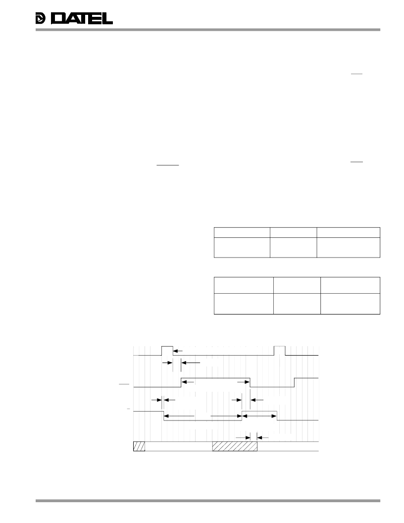
Figure 2. ADS-942A Timing Diagram
Note: Scale is approximately 25ns per division.
START
CONVERT
INTERNAL S/H
N
N+1
35ns max..
EOC
10ns typ.
15ns max.
OUTPUT
DATA
DATA N VALID
300ns min.
Hold
DATA N-1 VALID
30ns max.
35ns min., 50ns typ., 60 ns max
35ns typ.
350ns min.
150ns max.
Aquisition Time
INVALID DATA
200ns max.
Conversion Time
300ns typ., 325ns max.
相關PDF資料 |
PDF描述 |
|---|---|
| ADS-943 | 14-Bit, 3MHz, Low-Distortion Sampling A/D Converters |
| ADS-943GM | 14-Bit, 3MHz, Low-Distortion Sampling A/D Converters |
| ADS-943MC | 14-Bit, 3MHz, Low-Distortion Sampling A/D Converters |
| ADS-943MM | 14-Bit, 3MHz, Low-Distortion Sampling A/D Converters |
| ADS-943GC | 14-Bit, 3MHz, Low-Distortion Sampling A/D Converters |
相關代理商/技術參數 |
參數描述 |
|---|---|
| ADS-942MC | 制造商:Murata Power Solutions 功能描述:ADC Single 2-Step Flash 2Msps 14-bit Parallel 32-Pin PDIP |
| ADS-942ME | 制造商:未知廠家 制造商全稱:未知廠家 功能描述:Analog-to-Digital Converter, 14-Bit |
| ADS-942MM | 制造商:未知廠家 制造商全稱:未知廠家 功能描述:Analog-to-Digital Converter, 14-Bit |
| ADS-943 | 制造商:未知廠家 制造商全稱:未知廠家 功能描述:14-Bit, 3MHz, Low-Distortion Sampling A/D Converters |
| ADS-943/883 | 制造商:Murata Power Solutions 功能描述:ADC Single 2-Step Flash 3Msps 14-bit Parallel 24-Pin CDDIP |
發布緊急采購,3分鐘左右您將得到回復。