- 您現(xiàn)在的位置:買賣IC網(wǎng) > PDF目錄374036 > ADSP-2186BST-160 (ANALOG DEVICES INC) DSP Microcomputer PDF資料下載
參數(shù)資料
| 型號: | ADSP-2186BST-160 |
| 廠商: | ANALOG DEVICES INC |
| 元件分類: | 數(shù)字信號處理 |
| 英文描述: | DSP Microcomputer |
| 中文描述: | 24-BIT, 20 MHz, OTHER DSP, PQFP100 |
| 封裝: | METRIC, PLASTIC, TQFP-100 |
| 文件頁數(shù): | 12/36頁 |
| 文件大小: | 237K |
| 代理商: | ADSP-2186BST-160 |
第1頁第2頁第3頁第4頁第5頁第6頁第7頁第8頁第9頁第10頁第11頁當前第12頁第13頁第14頁第15頁第16頁第17頁第18頁第19頁第20頁第21頁第22頁第23頁第24頁第25頁第26頁第27頁第28頁第29頁第30頁第31頁第32頁第33頁第34頁第35頁第36頁
ADSP-2186
–12–
REV. A
I/O Space Instructions
The instructions used to access the ADSP-2186’s I/O memory
space are as follows:
Syntax:
IO(
addr
) =
dreg
dreg
= IO(
addr
);
where
addr
is an address value between 0 and 2047 and
dreg
is
any of the 16 data registers.
Examples:
IO(23) = AR0;
AR1 = IO(17);
Description:
The I/O space read and write instructions move
data between the data registers and the I/O
memory space.
DESIGNING AN EZ-ICE-COMPATIBLE SYSTEM
The ADSP-2186 has on-chip emulation support and an
ICE-Port, a special set of pins that interface to the EZ-ICE. These
features allow in-circuit emulation without replacing the target
system processor by using only a 14-pin connection from the
target system to the EZ-ICE. Target systems must have a 14-pin
connector to accept the EZ-ICE’s in-circuit probe, a 14-pin plug.
Emulation Reset and the Mode Pins
The Mode A, B, and C pins are located on the rising edge of the
RESET
signal. However, when the emulator reset (
ERESET
) is
asserted by the EZ-ICE, the DSP performs a chip reset, and the
initial mode information is erased, and the logic values on the
mode pins are latched. You must take into consideration the
value of the mode pins before issuing a chip reset command
from the EZ-ICE user interface. If you are using a passive
method of maintaining mode information (as discussed in Set-
ting Memory Modes) then it does not matter that the mode
information is latched by an emulator reset. However, if you are
using the
RESET
pin as a method of setting the value of the
mode pins, then you have to take into consideration the effects
of an emulator reset.
One method of ensuring that the values located on the mode
pins is the one that is desired to construct a circuit like the one
shown in Figure 9. This circuit will force the value located on
the Mode C pin to zero; regardless if it latched via the
RESET
or
ERESET
pin.
PROGRAMMABLE I/O
MODE A/PFO
RESET
ERESET
1k
V
ADSP-2186
Figure 9. Boot Mode Circuit
See the
ADSP-2100 Family EZ-Tools
data sheet for complete
information on ICE products.
The ICE-Port interface consists of the following ADSP-2186
pins:
EBR
EBG
ERESET
EMS
EINT
ECLK
ELIN
ELOUT
EE
These ADSP-2186 pins must be connected only to the EZ-ICE
connector in the target system. These pins have no function
except during emulation, and do not require pull-up or
pull-down resistors. The traces for these signals between the
ADSP-2186 and the connector must be kept as short as pos-
sible, no longer than three inches.
The following pins are also used by the EZ-ICE:
BR
BG
RESET
GND
The EZ-ICE uses the EE (emulator enable) signal to take con-
trol of the ADSP-2186 in the target system. This causes the
processor to use its
ERESET
,
EBR
and
EBG
pins instead of
the
RESET
,
BR
and
BG
pins. The
BG
output is three-stated.
These signals do not need to be jumper-isolated in your system.
The EZ-ICE connects to your target system via a ribbon cable
and a 14-pin female plug. The female plug is plugged onto the
14-pin connector (a pin strip header) on the target board.
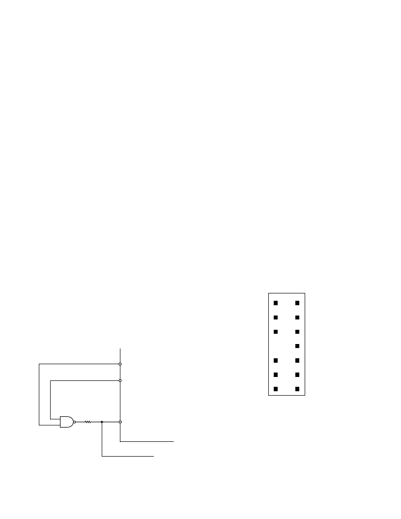
Target Board Connector for EZ-ICE Probe
The EZ-ICE connector (a standard pin strip header) is shown in
Figure 10. You must add this connector to your target board
design if you intend to use the EZ-ICE. Be sure to allow enough
room in your system to fit the EZ-ICE probe onto the 14-pin
connector.
1
2
3
4
5
6
7
8
9
10
11
12
13
14
GND
KEY (NO PIN)
RESET
BR
BG
TOP VIEW
EBG
EBR
ELOUT
EE
EINT
ELIN
ECLK
EMS
ERESET
Figure 10. Target Board Connector for EZ-ICE
The 14-pin, 2-row pin strip header is keyed at the Pin 7 loca-
tion—you must remove Pin 7 from the header. The pins must
be 0.025 inch square and at least 0.20 inch in length. Pin spac-
ing should be 0.1
×
0.1 inches. The pin strip header must have
at least 0.15-inch clearance on all sides to accept the EZ-ICE
probe plug. Pin strip headers are available from vendors such as
3M, McKenzie and Samtec.
相關PDF資料 |
PDF描述 |
|---|---|
| ADSP-2186KST-115 | DSP Microcomputer |
| ADSP-2186KST-133 | DSP Microcomputer |
| ADSP-2186KST-160 | DSP Microcomputer |
| ADSP-2186LBCA-160 | DSP Microcomputer |
| ADSP-2186LBST-115 | DSP Microcomputer |
相關代理商/技術參數(shù) |
參數(shù)描述 |
|---|---|
| ADSP-2186BST-160X | 制造商:未知廠家 制造商全稱:未知廠家 功能描述:16-Bit Digital Signal Processor |
| ADSP-2186BSTZ-115 | 制造商:Analog Devices 功能描述:DSP Fixed-Point 16-Bit 28.8MHz 28.8MIPS 100-Pin LQFP 制造商:Rochester Electronics LLC 功能描述: |
| ADSP-2186BSTZ-133 | 制造商:AD 制造商全稱:Analog Devices 功能描述:DSP Microcomputer |
| ADSP-2186BSTZ-160 | 功能描述:IC DSP CONTROLLER 16BIT 100LQFP RoHS:是 類別:集成電路 (IC) >> 嵌入式 - DSP(數(shù)字式信號處理器) 系列:ADSP-21xx 標準包裝:40 系列:TMS320DM64x, DaVinci™ 類型:定點 接口:I²C,McASP,McBSP 時鐘速率:400MHz 非易失內(nèi)存:外部 芯片上RAM:160kB 電壓 - 輸入/輸出:3.30V 電壓 - 核心:1.20V 工作溫度:0°C ~ 90°C 安裝類型:表面貼裝 封裝/外殼:548-BBGA,F(xiàn)CBGA 供應商設備封裝:548-FCBGA(27x27) 包裝:托盤 配用:TMDSDMK642-0E-ND - DEVELPER KIT W/NTSC CAMERA296-23038-ND - DSP STARTER KIT FOR TMS320C6416296-23059-ND - FLASHBURN PORTING KIT296-23058-ND - EVAL MODULE FOR DM642TMDSDMK642-ND - DEVELOPER KIT W/NTSC CAMERA |
| adsp-2186kst-1 | 制造商:Analog Devices 功能描述: |
發(fā)布緊急采購,3分鐘左右您將得到回復。