- 您現在的位置:買賣IC網 > PDF目錄379659 > AG2120 (Electronic Theatre Controls, Inc.) FULLY FEATURED PSTN INTERFACE PDF資料下載
參數資料
| 型號: | AG2120 |
| 廠商: | Electronic Theatre Controls, Inc. |
| 英文描述: | FULLY FEATURED PSTN INTERFACE |
| 中文描述: | 全功能PSTN接口 |
| 文件頁數: | 11/14頁 |
| 文件大小: | 256K |
| 代理商: | AG2120 |
V2.0 October 2002
Advance Data Sheet
Silver Telecom 2002
Page 11
Ag2120
FULLY FEATURED PSTN INTERFACE
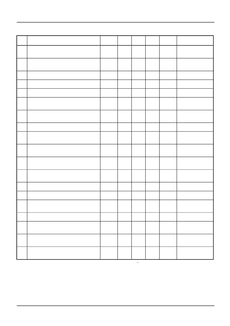
10.0 AC Electrical Characteristics.
Characteristic
Sym
Min
Typ*
Max
Units
Test Comments
1
1
Ringing voltage: detect
Ringing voltage: no detect
Ringing voltage: detect
Ringing voltage: no detect
V
RD
26
22
22
14
14
18
V
RMS
+5V operation
2
V
RD
18
10
V
RMS
+3.3V operation
3
Ringing frequency
F
R
15
68
Hz
4
Input Impedance at V
IN
100
k
5
Output impedance at V
out
Absolute voltage gain, 2 Wire to
V
OUT
Absolute voltage gain, V
IN
to
2 Wire
10
6
-0.5
+0.5
dB
Off-hook
7
-0.5
+0.5
dB
Off-Hook
8
On-hook gain, 2 Wire to V
OUT
Relative gain, referenced to
1kHz. 2Wire - V
out
, V
in
- 2Wire
Total harmonic distortion @
2Wire and V
out
Overload distortion @2 Wire and
V
out
-0.5
+0.5
dB
9
-0.5
+0.5
dB
200 - 3400 Hz
10
THD
0.1
1.0
%
@0dBm, 1kHz
11
2
OD
0.5
5.0
%
@+3dBm,
1kHz
50 – 500Hz
V
CM
= 60V
RMS
50 – 60Hz
12
Common mode rejection ratio
CMRR
70
75
dB
13
Common mode overload level
CMOL
250
300
V
RMS
14
Idle channel noise
3
N
C
12.0
dBrnC
@2 Wire & V
OUT
Ripple 0.1V,
1kHz on V
CC
300-3400Hz
15
Power supply rejection ratio
at 2 Wire and V
out
Return loss
PSRR
25
dB
16
4
RL
18
dB
17
Transhybrid loss
4
THL
18
21
60
40
dB
dB
300-3400Hz
500-2500Hz
200-1000Hz
1000-4000Hz
18
Metallic to longitudinal balance
70
70
dB
19
Leakage current, Tip or Ring to
analog ground
I
LA
5
mA
RMS
1000V ac
All AC Electrical Characteristics are over the Recommended Operating Conditions with V
at +5.0V +5%, unless otherwise stated.
*Typical figures are at 25°C with nominal 5V supply and 25mA loop current unless otherwise stated. These figures are for design aid only.
1 For test circuit details please contact Silver Telecom.
2 These figures fpr+5V operation. For +3.3V operation, OD is typically 5% at +3dBm.
3 In the off-hook condition
4 Into a 600
impedance
相關PDF資料 |
PDF描述 |
|---|---|
| AG2130 | LOW COST PSTN INTERFACE |
| AG2410 | HIGH PERFORMANCE QUAD TRUNK |
| AG603-89 | InGaP HBT Gain Block |
| AG603-86 | InGaP HBT Gain Block |
| AG603-86PCB | InGaP HBT Gain Block |
相關代理商/技術參數 |
參數描述 |
|---|---|
| AG2130 | 制造商:未知廠家 制造商全稱:未知廠家 功能描述:LOW COST PSTN INTERFACE |
| AG215W9B | 功能描述:3M AG21.5W9 ANTI-GLARE FILTER FO 制造商:3m 系列:* 零件狀態:在售 標準包裝:1 |
| AG220W1B | 功能描述:ANTI-GLARE FILTER 制造商:3m 系列:* 零件狀態:在售 標準包裝:5 |
| AG225-FLY11E3 | 制造商:Fuji Electric 功能描述: |
| AG230W9B | 功能描述:3M AG23.0W9 ANTI-GLARE FILTER FO 制造商:3m 系列:* 零件狀態:在售 標準包裝:1 |
發布緊急采購,3分鐘左右您將得到回復。