- 您現在的位置:買賣IC網 > PDF目錄379666 > AMC7580-X.XPF (Electronic Theatre Controls, Inc.) Cap-Free, NMOS, 150mA Low Dropout Regulator with Reverse Current Protection PDF資料下載
參數資料
| 型號: | AMC7580-X.XPF |
| 廠商: | Electronic Theatre Controls, Inc. |
| 元件分類: | 基準電壓源/電流源 |
| 英文描述: | Cap-Free, NMOS, 150mA Low Dropout Regulator with Reverse Current Protection |
| 中文描述: | 無電容,NMOS管,150mA的低壓差穩壓器的反向電流保護 |
| 文件頁數: | 5/12頁 |
| 文件大小: | 336K |
| 代理商: | AMC7580-X.XPF |
AMC DOC. #: AMC7580_E (LF)
Feb 2005
AMC7580
7A L
OW
D
ROPOUT
R
EGULATOR
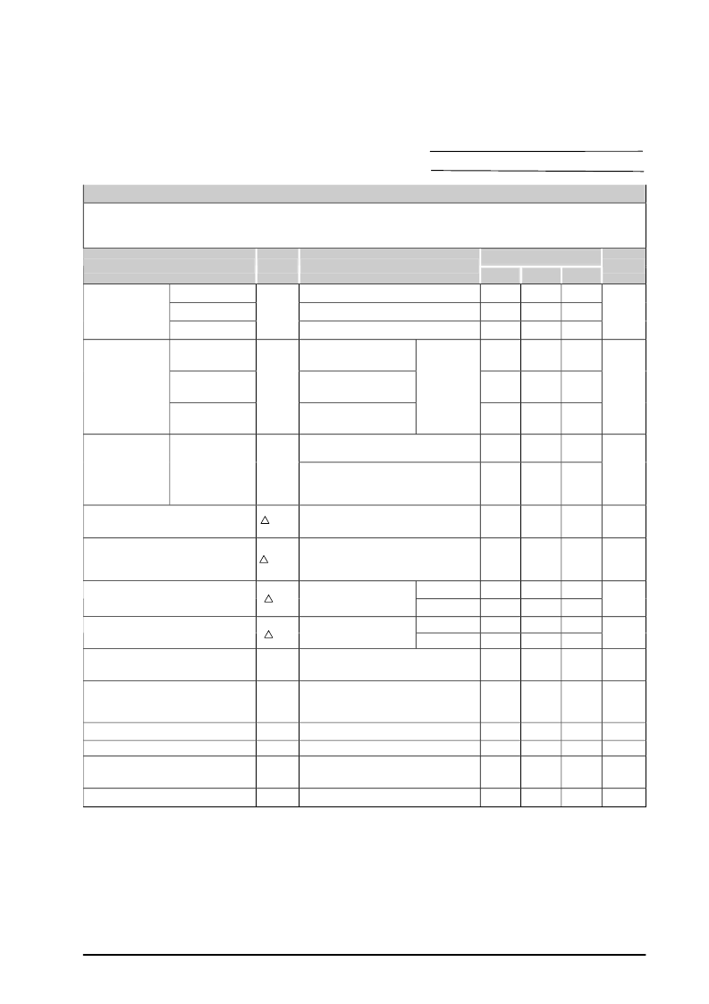
ELECTRICAL CHARACTERISTICS
Unless otherwise specified, these specifications apply T
J
= 25
°
C for AMC7580; I
O
= 10mA, V
OUT
= V
SENSE
, and are
for DC characteristics only. (Low duty cycle pulse testing techniques are used which maintains junction and case
temperatures equal to the ambient temperature.)
AMC7580
Typ.
Parameter
Symbol
Test Conditions
Min.
2.474 2.500 2.525
3.267 3.300 3.333
4.950 5.000 5.050
Max.
Units
AMC7580-2.5
AMC7580-3.3
AMC7580-5.0
V
CONTROL
= 5.0V, V
POWER
= 3.3V
V
CONTROL
= 5.8V, V
POWER
= 3.8V
V
CONTROL
= 7.5V, V
POWER
= 5.5V
V
CONTROL
= 5.0V,
V
POWER
= 3.3V
V
CONTROL
= 5.0V,
V
POWER
= 4.1V
V
CONTROL
= 6.5V,
V
POWER
= 5.8V
V
CONTROL
(Note 1)
V
CONTROL
= (V
OUT
+ 1.5V) to 12V,
V
POWER
= (V
OUT
+ 0.8V) to 7V,
I
O
= 10mA to 7A
(1.5V + V
OUT
)
≤
V
CONTROL
≤
12V,
0.8V
≤
(V
POWER
- V
OUT
)
≤
5.5V
V
CONTROL
= V
OUT
+ 2.5V,
V
POWER
= V
OUT
+ 0.8V,
I
O
= 10mA to 7A
Output Voltage
V
OUT
V
AMC7580-2.5
2.460 2.500 2.540
AMC7580-3.3
3.247 3.300 3.353
Output Voltage
AMC7580-5.0
V
OUT
I
O
= 7A
4.920 5.000 5.080
V
= 5.0V, V
POWER
= 3.3V,
1.238 1.250 1.262
Reference
Voltage
AMC7580-ADJ V
REF
1.230 1.250 1.270
V
Line Regulation (Note 2)
V
OI
0.04
0.2
%
Load regulation (Note 2)
V
OL
0.08
0.3
%
I
O
= 10mA
I
O
= 7A
I
O
= 10mA
I
O
= 7A
1.00
1.15
0.10
0.45
1.15
1.30
0.17
0.50
Dropout Voltage
V
CONTROL
- V
OUT
(Note 3)
V
V
POWER
= V
OUT
+ 0.8V
V
Dropout Voltage
V
POWER
- V
OUT
(Note 3)
V
V
CONTROL
= V
OUT
+
2.5V
V
CONTROL
= 2.75V,
V
POWER
= 2.05V, I
O
= 10mA
V
CONTROL
= V
OUT
+ 2.5V,
V
POWER
= V
OUT
+ 0.8V,
I
O
= 10mA to 7A
(V
IN
- V
OUT
)=1.5V
Imin V
CONTROL
= 5.0V, V
POWER
= 3.3V
V
CONTROL
= V
POWER
= V
OUT
+ 2.5V,
V
RIPPLE
= 1V
PP
, I
O
= 2.5A
T
A
= 25
°
C
V
Adjust Pin Current
I
ADJ
50
120
μ
A
Control Pin Current
I
CTNL
80
135
mA
Current Limit
Minimum Load Current (Note 4)
I
CL
7
8
5
A
mA
10
Ripple Rejection (Note 5)
R
R
60
80
dB
Thermal Regulation
0.003
% / W
Note 1 Output voltage is set to be 2.5V.
Note 2:
differential and the output current. However, the maximum power will not be available over the full
input/output voltage range.
Note 3: The dropout voltage is measured by either minimum control voltage or power voltage. The specifications
represent the minimum input/output voltage required to maintain 1% regulation.
Note 4: The minimum load current is the minimum current required to maintain regulation. Normally the current in
the resistor divider used to set the output voltage is selected to meet the minimum load current requirement.
Note 5: These parameters, although guaranteed, are not tested in production prior to shipment
Line and load regulations are guaranteed up to maximum power dissipation determined by input/output
Copyright
2002, ADD Microtech Corp.
5
www.addmtek.com
相關PDF資料 |
PDF描述 |
|---|---|
| AMC7581 | Cap-Free, NMOS, 150mA Low Dropout Regulator with Reverse Current Protection |
| AMC7581-2.5 | Hook-Up Wire; Conductor Size AWG:12; No. Strands x Strand Size:65 x 30; Jacket Color:Green; Cable/Wire MIL SPEC:MIL-W-76C Type MW; Conductor Material:Copper; Conductor Plating:Tin; Jacket Material:Polyvinylchloride (PVC) RoHS Compliant: Yes |
| AMC7581-1.8 | Cap-Free, NMOS, 150mA Low Dropout Regulator with Reverse Current Protection |
| AMC7581-3.3 | ECONOLINE: REC3-S_DRW(Z)/H* - 3W DIP Package- 1kVDC Isolation- Wide Input 2:1 & 4:1- Regulated Output- 100% Burned In- UL94V-0 Package Material- Continuous Short Circiut Protection- Efficiency to 80% |
| AMC7581-5.0 | Cap-Free, NMOS, 150mA Low Dropout Regulator with Reverse Current Protection |
相關代理商/技術參數 |
參數描述 |
|---|---|
| AMC7581 | 制造商:未知廠家 制造商全稱:未知廠家 功能描述:5A LOW DROPOUT REGULATOR |
| AMC7581-1.8 | 制造商:未知廠家 制造商全稱:未知廠家 功能描述:5A LOW DROPOUT REGULATOR |
| AMC7581-2.5 | 制造商:未知廠家 制造商全稱:未知廠家 功能描述:5A LOW DROPOUT REGULATOR |
| AMC7581-3.3 | 制造商:未知廠家 制造商全稱:未知廠家 功能描述:5A LOW DROPOUT REGULATOR |
| AMC7581-5.0 | 制造商:未知廠家 制造商全稱:未知廠家 功能描述:5A LOW DROPOUT REGULATOR |
發布緊急采購,3分鐘左右您將得到回復。