- 您現在的位置:買賣IC網 > PDF目錄76799 > AP108 (TELEDYNE COUGAR INC) 1 MHz - 150 MHz RF/MICROWAVE WIDE BAND MEDIUM POWER AMPLIFIER PDF資料下載
參數資料
| 型號: | AP108 |
| 廠商: | TELEDYNE COUGAR INC |
| 元件分類: | 放大器 |
| 英文描述: | 1 MHz - 150 MHz RF/MICROWAVE WIDE BAND MEDIUM POWER AMPLIFIER |
| 封裝: | TO-8, 3 PIN |
| 文件頁數: | 1/2頁 |
| 文件大小: | 108K |
| 代理商: | AP108 |
AP108
1 TO 150 MHz
TO-8 CASCADABLE AMPLIFIER
AP108
408-522-3838 Fax: 408-522-3839 Check for updates: www.teledyne-cougar.com
2/99
* Measured in a 50-ohm system at +15 Vdc unless otherwise specified.
^ 1.0 dBm lower below 2 MHz
Typical Values
AP108
High Output Power . . . . . . . . . . . . . . . . . . . . . . . . . . . . . . . .
+25.0 dBm
High Third Order I.P. . . . . . . . . . . . . . . . . . . . . . . . . . . . . . . .
+43 dBm
Medium Gain . . . . . . . . . . . . . . . . . . . . . . . . . . . . . . . . . . . . .
15.0 dB
Low Noise Figure . . . . . . . . . . . . . . . . . . . . . . . . . . . . . . . . .
3.3 dB
High Performance Thin Film
Standard Size TO-8 Package
Available in Surface Mount
Small Signal Gain (Min.)
15.0 dB
14.5 dB
14.0 dB
Gain Flatness (Max.)
±0.3 dB
±0.4 dB
±0.5 dB
Noise Figure (Max.)
10-150 MHz
3.3 dB
4.0 dB
4.5 dB
SWR (Max.)
Input/Output
<1.5:1
1.9:1
2.0:1
Power Output (Min.)
@ 1 dB comp.
+25.0^ dBm
+24.0^ dBm
+23.5^ dBm
DC Current (Max.)
109.0 mA
112.0 mA
115.0 mA
Guaranteed
Parameter
Typical
0 to 50° C
-55 to +85° C
Frequency (Min.)
1-250 MHz
1-150 MHz
Typical @ 25° C
+12 volts
+15 volts
Second Order Harmonic Intercept Point . . . . .
+66 dBm
Second Order Two Tone Intercept Point. . . . . .
+60 dBm
Third Order Two Tone Intercept Point. . . . . . . .
+40 dBm
+43 dBm
Storage Temperature . . . . . . . . . . . . . . . . . . . . . . . . . . . . . . -62 to +125° C
Maximum Case Temperature . . . . . . . . . . . . . . . . . . . . . . . .
+125° C
Maximum DC Voltage . . . . . . . . . . . . . . . . . . . . . . . . . . . . . .
+17 Volts
Maximum Continuous RF Input Power . . . . . . . . . . . . . . . .
+17 dBm
Maximum Short Term Input Power (1 Minute Max.) . . . . . .
100 Milliwatts
Maximum Peak Power (3 sec Max.) . . . . . . . . . . . . . . . . . .
0.5 Watt
Burn-in Temperature . . . . . . . . . . . . . . . . . . . . . . . . . . . . . .
+100° C
Thermal Resistance1 (
θjc) . . . . . . . . . . . . . . . . . . . . . . . . . . +25° C/Watt
Junction Temperature Rise Above Case (Tjc) . . . . . . . . . .
+43° C
1 Thermal resistance is based on total power dissipation.
ABSOLUTE MAXIMUM RATINGS
INTERMODULATION PERFORMANCE
SPECIFICATIONS*
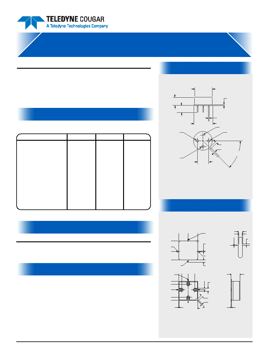
TO-8 Package for Amplifiers
SMTO-8 Package for Amplifiers
0
50 INPUT
0.250
(6.35)
0.450
(11.43)
0
0.075
(1.91)
0.350
(8.89)
0.200
(5.08)
0.450
(11.43)
0
.2
2
5
(5
.7
2
)
0
.4
5
0
(1
1
.4
3
)
0
.0
7
5
(1
.9
1
)
0
.2
2
5
(5
.7
2
)
0
.3
7
5
(9
.5
3
)
50 OUTPUT
0.040 0.012
(1.02 0.30)
(4) PLCS
DC BIAS
0.016 0.002
(0.41 0.05)
(4) PLCS
GND
0.050
(1.27)
(4) PLCS
0.100
(2.54)
(4) PLCS
0.010
(0.25)
0.008 0.001
(0.20 0.03)
0.170
(4.32)
(TYP.)
0.031
(0.79)
0.031
(0.79)
45
0.016 0.002
0.010 0.002
0.008
0.012
SEE
DETAIL "A"
DETAIL A
(NO SCALE)
If DC is present on RF input/output, this model
requires additional external blocking capacitors.
DIMENSIONS ARE IN INCHES (MILLIMETERS)
APS108
50 OHM INPUT
+DC VOLTAGE
0.031 (0.79)
50 OHM OUTPUT
GROUND
45°± 3°
0.033 (0.84)
0.018±0.002
(0.46±0.05)
(4) PLCS
0.300
(7.62)
DIA. B.C.
0.504 (12.80)
DIA.
0.025
(0.64)
0.450 (11.43)
DIA.
0.208 (5.28)
MAX.
0.185±0.015
(4.70±0.38)
DIA. PIN
相關PDF資料 |
PDF描述 |
|---|---|
| AMF-3F-275310-60-17P | 27500 MHz - 31000 MHz RF/MICROWAVE WIDE BAND LOW POWER AMPLIFIER |
| AMF-5F-177220-50-20P | 17700 MHz - 22000 MHz RF/MICROWAVE WIDE BAND MEDIUM POWER AMPLIFIER |
| AMF-6F-180265-50-17P | 18000 MHz - 26500 MHz RF/MICROWAVE WIDE BAND LOW POWER AMPLIFIER |
| AMF-6F-200400-90-22P | 20000 MHz - 40000 MHz RF/MICROWAVE WIDE BAND MEDIUM POWER AMPLIFIER |
| AMF-6F-275310-50-17P | 27500 MHz - 31000 MHz RF/MICROWAVE WIDE BAND LOW POWER AMPLIFIER |
相關代理商/技術參數 |
參數描述 |
|---|---|
| AP1080 | 制造商:未知廠家 制造商全稱:未知廠家 功能描述:TRANSISTOR | BJT | PNP | 140V V(BR)CEO | 50A I(C) | TO-210AE |
| AP1080-2000-1 | 制造商:BARBER - COLMAN 功能描述:ACTION PAK LIMIT ALARM DC VOLTAGE/CURRENT INPUT, 11 PIN, SINGLE TRIP (DPDT) 120 |
| AP1080-2000-D | 制造商:Eurotherm Inc 功能描述:ACTION PAK DC INPUT SINGLE TRIP 24VDC POWER |
| AP1081 | 制造商:未知廠家 制造商全稱:未知廠家 功能描述:TRANSISTOR | BJT | PNP | 140V V(BR)CEO | 25A I(C) | TO-3 |
| AP1082 | 制造商:未知廠家 制造商全稱:未知廠家 功能描述:TRANSISTOR | BJT | PNP | 140V V(BR)CEO | 20A I(C) | TO-210AE |
發布緊急采購,3分鐘左右您將得到回復。