- 您現在的位置:買賣IC網 > PDF目錄51262 > APT15GN120KG 45 A, 1200 V, N-CHANNEL IGBT, TO-220AB PDF資料下載
參數資料
| 型號: | APT15GN120KG |
| 元件分類: | IGBT 晶體管 |
| 英文描述: | 45 A, 1200 V, N-CHANNEL IGBT, TO-220AB |
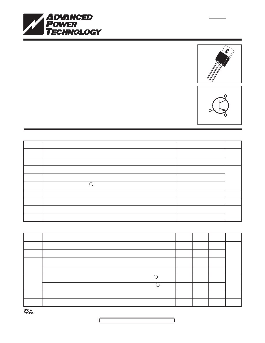
| 封裝: | ROHS COMPLIANT, TO-220, 3 PIN |
| 文件頁數: | 1/6頁 |
| 文件大小: | 192K |
| 代理商: | APT15GN120KG |
050-7599
Rev
B
10-2005
APT15GN120K(G)
TYPICAL PERFORMANCE CURVES
MAXIMUM RATINGS
All Ratings: T
C = 25°C unless otherwise specied.
STATIC ELECTRICAL CHARACTERISTICS
Characteristic / Test Conditions
Collector-Emitter Breakdown Voltage (V
GE = 0V, I C = 0.5mA)
Gate Threshold Voltage (V
CE = VGE, I C = 600A, Tj = 25°C)
Collector-Emitter On Voltage (V
GE = 15V, IC = 15A, Tj = 25°C)
Collector-Emitter On Voltage (V
GE = 15V, IC = 15A, Tj = 125°C)
Collector Cut-off Current (V
CE = 1200V, VGE = 0V, Tj = 25°C)
2
Collector Cut-off Current (V
CE = 1200V, VGE = 0V, Tj = 125°C)
2
Gate-Emitter Leakage Current (V
GE = ±20V)
Intergrated Gate Resistor
Symbol
V
(BR)CES
V
GE(TH)
V
CE(ON)
I
CES
I
GES
R
GINT
Units
Volts
A
nA
Symbol
V
CES
V
GE
I
C1
I
C2
I
CM
SSOA
P
D
T
J,TSTG
T
L
APT15GN120K(G)
1200
±30
45
22
45
45A @ 1200V
195
-55 to 150
300
UNIT
Volts
Amps
Watts
°C
Parameter
Collector-Emitter Voltage
Gate-Emitter Voltage
Continuous Collector Current @ T
C = 25°C
Continuous Collector Current @ T
C = 110°C
Pulsed Collector Current 1
Switching Safe Operating Area @ T
J = 150°C
Total Power Dissipation
Operating and Storage Junction Temperature Range
Max. Lead Temp. for Soldering: 0.063" from Case for 10 Sec.
APT Website - http://www.advancedpower.com
CAUTION: These Devices are Sensitive to Electrostatic Discharge. Proper Handling Procedures Should Be Followed.
Utilizing the latest Field Stop and Trench Gate technologies, these IGBT's have ultra
low VCE(ON) and are ideal for low frequency applications that require absolute minimum
conduction loss. Easy paralleling is a result of very tight parameter distribution and a
slightly positive VCE(ON) temperature coefcient. Low gate charge simplies gate drive
design and minimizes losses.
1200V Field Stop
Trench Gate: Low VCE(on)
Easy Paralleling
Applications: Welding, Inductive Heating, Solar Inverters, SMPS, Motor drives, UPS
MIN
TYP
MAX
1200
5.0
5.8
6.5
1.4
1.7
2.1
2.0
100
TBD
120
N/A
1200V
APT15GN120K
APT15GN120KG*
*G Denotes RoHS Compliant, Pb Free Terminal Finish.
G
C
E
TO-220
相關PDF資料 |
PDF描述 |
|---|---|
| APT15GN120K | 45 A, 1200 V, N-CHANNEL IGBT, TO-220AB |
| APT15GP90BDQ1 | 43 A, 900 V, N-CHANNEL IGBT, TO-247AD |
| APT15GP90BDQ1G | 43 A, 900 V, N-CHANNEL IGBT, TO-247AD |
| APT15GP90BDQ1G | 43 A, 900 V, N-CHANNEL IGBT, TO-247AD |
| APT15GP90BDQ1 | 43 A, 900 V, N-CHANNEL IGBT, TO-247AD |
相關代理商/技術參數 |
參數描述 |
|---|---|
| APT15GN120SDQ1 | 制造商:MICROSEMI 制造商全稱:Microsemi Corporation 功能描述:High Speed PT IGBT |
| APT15GN120SDQ1G | 制造商:MICROSEMI 制造商全稱:Microsemi Corporation 功能描述:High Speed PT IGBT |
| APT15GP60B | 制造商:MICROSEMI 制造商全稱:Microsemi Corporation 功能描述:POWER MOS 7 IGBT |
| APT15GP60BDF1 | 制造商:ADPOW 制造商全稱:Advanced Power Technology 功能描述:POWER MOS 7 IGBT |
| APT15GP60BDL | 制造商:MICROSEMI 制造商全稱:Microsemi Corporation 功能描述:Resonant Mode Combi IGBT |
發布緊急采購,3分鐘左右您將得到回復。