- 您現在的位置:買賣IC網 > Datasheet目錄60 > AS5510-DWLT (ams)IC ENCODER MAGNETIC LIN 6-WLCSP Datasheet資料下載
參數資料
| 型號: | AS5510-DWLT |
| 廠商: | ams |
| 文件頁數: | 10/19頁 |
| 文件大小: | 248K |
| 描述: | IC ENCODER MAGNETIC LIN 6-WLCSP |
| 標準包裝: | 12,000 |
| 傳感范圍: | ±50mT |
| 類型: | 線性 |
| 電源電壓: | 2.5 V ~ 3.6 V |
| 電流 - 電源: | 3.5mA |
| 電流 - 輸出(最大): | 20mA |
| 輸出類型: | 數字式,開漏極 |
| 工作溫度: | -30°C ~ 85°C |
| 封裝/外殼: | * |
| 供應商設備封裝: | * |
| 包裝: | * |
www.ams.com/AS5510
Revision 0.1
9 - 18
AS5510
Datasheet - Detailed Description
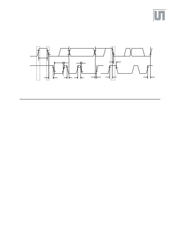
Figure 5. I睠 Timing Diagram
7.3 I睠 Modes
The AS5510 supports the I睠 bus protocol. A device that sends data onto the bus is defined as a transmitter and a device receiving data as a
receiver. The device that controls the message is called a master. The devices that are controlled by the master are referred to as slaves. A
master device that generates the serial clock (SCL), controls the bus access and generates the START and STOP conditions must control the
bus. The AS5510 operates as a slave on the I睠 bus. Within the bus specifications a standard mode (100 kHz maximum clock rate) a fast mode
(400 kHz maximum clock rate) and fast mode plus (1MHz maximum clock rate) are defined. The AS5510 works in all three modes. Connections
to the bus are made through the open-drain I/O lines SDA and the input SCL. Clock stretching is not included.
The following bus protocol has been defined:
n Data transfer may be initiated only when the bus is not busy.
n During data transfer, the data line must remain stable whenever the clock line is HIGH. Changes in the data line while the clock line is HIGH
are interpreted as start or stop signals.
Accordingly, the following bus conditions have been defined:
Bus Not Busy. Both data and clock lines remain HIGH.
Start Data Transfer. A change in the state of the data line, from HIGH to LOW, while the clock is HIGH, defines a START condition.
Stop Data Transfer. A change in the state of the data line, from LOW to HIGH, while the clock line is HIGH, defines the STOP condition.
Data Valid. The state of the data line represents valid data when, after a START condition, the data line is stable for the duration of the HIGH
period of the clock signal. The data on the line must be changed during the LOW period of the clock signal. There is one clock pulse per bit of
data. Each data transfer is initiated with a START condition and terminated with a STOP condition. The number of data bytes transferred
between START and STOP conditions are not limited, and are determined by the master device. The information is transferred byte-wise and
each receiver acknowledges with a ninth bit.
Acknowledge. Each receiving device, when addressed, is obliged to generate an acknowledge bit after the reception of each byte. The
master device must generate an extra clock pulse that is associated with this acknowledge bit.A device that acknowledges must pull down the
SDA line during the acknowledge clock pulse in such a way that the SDA line is stable LOW during the HIGH period of the acknowledge-related
clock pulse. Of course, setup and hold times must be taken into account. A master must signal an end of READ access to the slave by not
generating an acknowledge bit on the last byte that has been clocked out of the slave. In this case, the slave must leave the data line HIGH to
enable the master to generate the STOP condition.
DA
CL
Start
Stop
t
buf
t
LOW
t
R
tHD.STA
t
HIGH
tF
t
SU.DAT
t
SU.STA
tHD.STA
t
SU.STO
Repeated
Start
t
HD.DAT
相關PDF資料 |
PDF描述 |
|---|---|
| ATS137-PL-B-B | IC HALL SENSOR SGL 25MA SIP-3L |
| ATS177-PG-B-B | IC HALL SENSOR LATCH 25MA SIP-3L |
| ATS617LSGTN-T | IC HALL EFFECT GEAR SENSOR 4SIP |
| ATS625LSGTN-T | IC SENSOR GEAR TOOTH 4-SIP |
| ATS627LSGTN-T | IC HALL EFFECT GEAR SENSOR 4-SIP |
相關代理商/技術參數 |
參數描述 |
|---|---|
| AS5510-DWLT-1K | 功能描述:板機接口霍耳效應/磁性傳感器 RoHS:否 制造商:Honeywell 類型:Bipolar Hall-Effect Digital Position Sensor 工作電源電壓:3 V to 24 V 電源電流:3.5 mA 最大輸出電流:20 mA 工作點最小值/最大值:5 G, 55 G 最小/最大釋放點(Brp):- 55 G, - 5 G 最大工作溫度:+ 150 C 安裝風格:SMD/SMT 封裝 / 箱體:SOT-23 |
| AS5510-SO_EK_AB | 功能描述:AS5510 - Magnetic, Linear Position Sensor Evaluation Board 制造商:ams 系列:- 零件狀態:有效 傳感器類型:磁性,線性位置 感應范圍:- 接口:I2C 靈敏度:- 電壓 - 電源:2.5 V ~ 3.6 V 嵌入式:- 所含物品:板 使用的 IC/零件:AS5510 標準包裝:1 |
| AS5510-WL_EK_AB | 功能描述:AS5510 - Magnetic, Linear Position Sensor Evaluation Board 制造商:ams 系列:- 零件狀態:有效 傳感器類型:磁性,線性位置 感應范圍:- 接口:I2C 靈敏度:- 電壓 - 電源:2.5 V ~ 3.6 V 嵌入式:- 所含物品:板 使用的 IC/零件:AS5510 標準包裝:1 |
| AS5510-WL_EK_DB | 功能描述:AS5510 - Magnetic, Linear Position Sensor Evaluation Board 制造商:ams 系列:- 零件狀態:有效 傳感器類型:磁性,線性位置 感應范圍:- 接口:I2C 靈敏度:- 電壓 - 電源:5V USB 或 9V 嵌入式:是,MCU,8 位 所含物品:板 使用的 IC/零件:AS5510 標準包裝:1 |
| AS55110FLF | 制造商:TT Electronics / IRC 功能描述:AS55110FLF |
發布緊急采購,3分鐘左右您將得到回復。