- 您現在的位置:買賣IC網 > PDF目錄369507 > BT137B-500G (NXP SEMICONDUCTORS) Triacs(雙向可控硅) PDF資料下載
參數資料
| 型號: | BT137B-500G |
| 廠商: | NXP SEMICONDUCTORS |
| 元件分類: | 晶閘管 |
| 英文描述: | Triacs(雙向可控硅) |
| 中文描述: | 500 V, 8 A, 4 QUADRANT LOGIC LEVEL TRIAC, TO-263 |
| 封裝: | PLASTIC, SOT-404, 3 PIN |
| 文件頁數: | 1/6頁 |
| 文件大小: | 52K |
| 代理商: | BT137B-500G |
Philips Semiconductors
Product specification
Triacs
BT137B series
GENERAL DESCRIPTION
QUICK REFERENCE DATA
Passivatedtriacsinaplasticenvelope
suitable
for
surface
intended for use
requiring high bidirectional transient
and blocking voltage capability and
high thermal cycling performance.
Typical applications include motor
control,
industrial
lighting, heating and static switching.
SYMBOL
PARAMETER
MAX.
MAX.
MAX. UNIT
mounting,
applications
in
BT137B-
BT137B-
BT137B-
500
500F
500G
500
600
600F
600G
600
800
800F
800G
800
V
DRM
Repetitive peak off-state
voltages
RMS on-state current
Non-repetitive peak on-state
current
V
and
domestic
I
T(RMS)
I
TSM
8
65
8
65
8
A
A
65
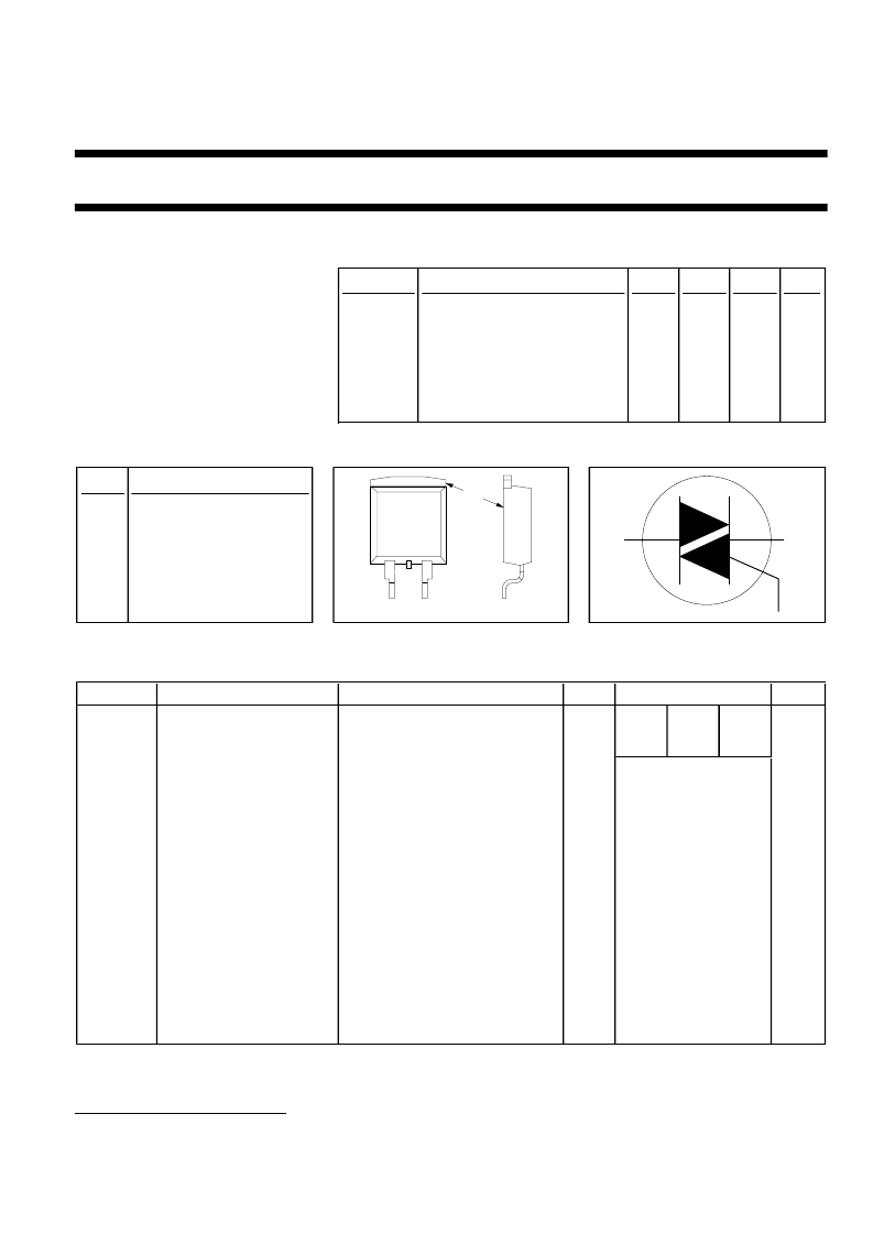
PINNING - SOT404
PIN CONFIGURATION
SYMBOL
PIN
DESCRIPTION
1
main terminal 1
2
main terminal 2
3
gate
mb
main terminal 2
LIMITING VALUES
Limiting values in accordance with the Absolute Maximum System (IEC 134).
SYMBOL
PARAMETER
CONDITIONS
MIN.
MAX.
-600
600
1
UNIT
-500
500
1
-800
800
V
DRM
Repetitive peak off-state
voltages
RMS on-state current
Non-repetitive peak
on-state current
-
V
I
T(RMS)
I
TSM
full sine wave; T
mb
≤
102 C
full sine wave; T
j
= 25 C prior to
surge
t = 20 ms
t = 16.7 ms
t = 10 ms
I
TM
= 12 A; I
= 0.2 A;
dI
G
/dt = 0.2 A/
μ
s
-
8
A
-
-
-
65
71
21
A
A
I
2
t
dI
T
/dt
I
2
t for fusing
Repetitive rate of rise of
on-state current after
triggering
A
2
s
T2+ G+
T2+ G-
T2- G-
T2- G+
-
-
-
-
-
-
-
-
50
50
50
10
2
5
5
0.5
150
125
A/
μ
s
A/
μ
s
A/
μ
s
A/
μ
s
A
V
W
W
C
C
I
GM
V
GM
P
GM
P
G(AV)
T
stg
T
j
Peak gate current
Peak gate voltage
Peak gate power
Average gate power
Storage temperature
Operating junction
temperature
over any 20 ms period
-40
-
1
3
mb
2
T1
T2
G
1
Although not recommended, off-state voltages up to 800V may be applied without damage, but the triac may
switch to the on-state. The rate of rise of current should not exceed 6 A/
μ
s.
June 1999
1
Rev 1.300
相關PDF資料 |
PDF描述 |
|---|---|
| BT137B-600G | Triacs(雙向可控硅) |
| BT137B-500F | Triacs(雙向可控硅) |
| BT137B-600F | 1-of-8 Decoder 20-LCCC -55 to 125 |
| BT136F-600D | Electrical Outlet Connector; Leaded Process Compatible:Yes; RoHS Compliant:Yes |
| BT136F-600E | Thyristor Product Catalog |
相關代理商/技術參數 |
參數描述 |
|---|---|
| BT137B500T/R | 制造商:未知廠家 制造商全稱:未知廠家 功能描述:TRIAC|500V V(DRM)|8A I(T)RMS|SOT-404 |
| BT137B-600 | 制造商:NXP Semiconductors 功能描述:TRIAC 8A 600V SOT-404 |
| BT137B-600D | 制造商:PHILIPS 制造商全稱:NXP Semiconductors 功能描述:Triacs logic level |
| BT137B600DT/R | 制造商:未知廠家 制造商全稱:未知廠家 功能描述:TRIAC|600V V(DRM)|8A I(T)RMS|SOT-404 |
| BT137B-600E | 制造商:NXP Semiconductors 功能描述: |
發布緊急采購,3分鐘左右您將得到回復。