- 您現在的位置:買賣IC網 > PDF目錄369523 > BTA225BSERIESC (NXP Semiconductors N.V.) Transient Voltage Suppressor Diodes PDF資料下載
參數資料
| 型號: | BTA225BSERIESC |
| 廠商: | NXP Semiconductors N.V. |
| 元件分類: | TVS-瞬態抑制二極管 |
| 英文描述: | Transient Voltage Suppressor Diodes |
| 中文描述: | 三高減刑象限可控硅 |
| 文件頁數: | 1/4頁 |
| 文件大小: | 22K |
| 代理商: | BTA225BSERIESC |
Philips Semiconductors
Preliminary specification
Three quadrant triacs
high commutation
BTA225B series C
GENERAL DESCRIPTION
QUICK REFERENCE DATA
Glass passivated high commutation
triacsinaplasticenvelopesuitablefor
surface mounting, intended for use in
circuitswherehighstaticanddynamic
dV/dt and high dI/dt can occur. These
devices will commutate the full rated
rms current at the maximum rated
junction temperature, without the aid
of a snubber.
SYMBOL
PARAMETER
MAX.
MAX.
MAX. UNIT
BTA225B-
500C
500
600C
600
800C
800
V
DRM
Repetitive peak off-state
voltages
RMS on-state current
Non-repetitive peak on-state
current
V
I
T(RMS)
I
TSM
25
180
25
180
25
180
A
A
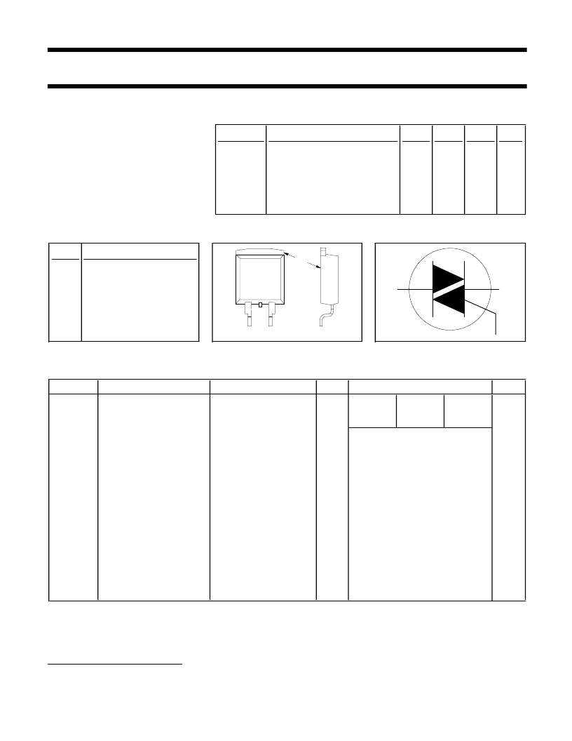
PINNING - SOT404
PIN CONFIGURATION
SYMBOL
PIN
DESCRIPTION
1
main terminal 1
2
main terminal 2
3
gate
mb
main terminal 2
LIMITING VALUES
Limiting values in accordance with the Absolute Maximum System (IEC 134).
SYMBOL PARAMETER
CONDITIONS
MIN.
MAX.
-600
600
1
UNIT
-500
500
1
-800
800
V
DRM
Repetitive peak off-state
voltages
RMS on-state current
-
V
I
T(RMS)
full sine wave;
T
≤
91 C
full sine wave;
T
j
= 25 C prior to surge
-
25
A
I
TSM
Non-repetitive peak
on-state current
t = 20 ms
t = 16.7 ms
t = 10 ms
I
TM
= 30 A; I
= 0.2 A;
dI
G
/dt = 0.2 A/
μ
s
-
-
-
190
209
180
100
A
A
I
2
t
dI
T
/dt
I
2
t for fusing
Repetitive rate of rise of
on-state current after
triggering
Peak gate current
Peak gate voltage
Peak gate power
Average gate power
Storage temperature
Operating junction
temperature
A
2
s
A/
μ
s
I
GM
V
GM
P
GM
P
G(AV)
T
stg
T
j
-
-
-
-
2
5
5
A
V
W
W
C
C
over any 20 ms period
0.5
150
125
-40
-
1
3
mb
2
T1
T2
G
1
Although not recommended, off-state voltages up to 800V may be applied without damage, but the triac may
switch to the on-state. The rate of rise of current should not exceed 15 A/
μ
s.
October 1997
1
Rev 1.000
相關PDF資料 |
PDF描述 |
|---|---|
| BTA40-200B | TRIAC|200V V(DRM)|40A I(T)RMS|SOT-93 |
| BTA40-200A | THYRISTOR MODULE|TRIAC |
| BTA40-400A | TRIAC ISOLIERTER INNENAUFBAU 40A 400V |
| BTA40-400B | THYRISTOR MODULE|TRIAC |
| BTA40-600A | TRIAC ISOLIERTER INNENAUFBAU 40A 600V |
相關代理商/技術參數 |
參數描述 |
|---|---|
| BTA225SERIESB | 制造商:PHILIPS 制造商全稱:NXP Semiconductors 功能描述:Three quadrant triacs high commutation |
| BTA225SERIESC | 制造商:未知廠家 制造商全稱:未知廠家 功能描述:Three quadrant triacs high commutation |
| BTA22B | 制造商:未知廠家 制造商全稱:未知廠家 功能描述:10-A SILICON TRIACS |
| BTA22C | 制造商:未知廠家 制造商全稱:未知廠家 功能描述:10-A SILICON TRIACS |
| BTA2-2C-240VAC | 制造商:BETA ELECTRIC INDUSTRY 功能描述:13A DPCO RELAY 240VAC |
發布緊急采購,3分鐘左右您將得到回復。