- 您現(xiàn)在的位置:買(mǎi)賣(mài)IC網(wǎng) > PDF目錄374053 > C062G102F1CH5CM (KEMET Corporation) MILITARY SPECIFCATIONS ON BACK PDF資料下載
參數(shù)資料
| 型號(hào): | C062G102F1CH5CM |
| 廠商: | KEMET Corporation |
| 英文描述: | MILITARY SPECIFCATIONS ON BACK |
| 中文描述: | 背面軍事SPECIFCATIONS |
| 文件頁(yè)數(shù): | 35/40頁(yè) |
| 文件大小: | 580K |
| 代理商: | C062G102F1CH5CM |
第1頁(yè)第2頁(yè)第3頁(yè)第4頁(yè)第5頁(yè)第6頁(yè)第7頁(yè)第8頁(yè)第9頁(yè)第10頁(yè)第11頁(yè)第12頁(yè)第13頁(yè)第14頁(yè)第15頁(yè)第16頁(yè)第17頁(yè)第18頁(yè)第19頁(yè)第20頁(yè)第21頁(yè)第22頁(yè)第23頁(yè)第24頁(yè)第25頁(yè)第26頁(yè)第27頁(yè)第28頁(yè)第29頁(yè)第30頁(yè)第31頁(yè)第32頁(yè)第33頁(yè)第34頁(yè)當(dāng)前第35頁(yè)第36頁(yè)第37頁(yè)第38頁(yè)第39頁(yè)第40頁(yè)
KEMET Electronics Corporation, P.O. Box 5928, Greenville, S.C. 29606, (864) 963-6300
35
APPLICATION NOTES FOR MULTILAYER CERAMIC CAPACITORS
A
ELECTRICAL CHARACTERISTICS
The fundamental electrical properties of multilayer
ceramic capacitors are as follows:
Polarity:
Multilayer ceramic capacitors are not polar,
and may be used with DC voltage applied in either direction.
Rated Voltage:
This term refers to the maximum con-
tinuous DC working voltage permissible across the entire
operating temperature range. Multilayer ceramic capacitors
are not extremely sensitive to voltage, and brief applications
of voltage above rated will not result in immediate failure.
However, reliability will be reduced by exposure to sustained
voltages above rated.
Capacitance:
The standard unit of capacitance is the
farad. For practical capacitors, it is usually expressed in
microfarads (10
-6
farad), nanofarads (10
-9
farad), or picofarads
(10
-12
farad). Standard measurement conditions are as
follows:
Class I (up to 1,000 pF):
1MHz and 1.2 VRMS
maximum.
1kHz and 1.2 VRMS
maximum.
1 kHz and 1.0 ± 0.2 VRMS.
1 kHz and 0.5 ± 0.1 VRMS.
Class I (over 1,000 pF):
Class II:
Class III:
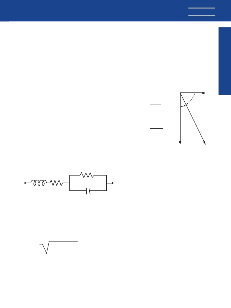
Like all other practical capacitors, multilayer ceramic
capacitors also have resistance and inductance. A simplified
schematic for the equivalent circuit is shown in Figure 1.
Other significant electrical characteristics resulting from
these additional properties are as follows:
Impedance:
Since the parallel resistance (Rp) is nor-
mally very high, the total impedance of the capacitor is:
Figure 1
C = Capacitance
L = Inductance
RS = Equivalent Series Resistance (ESR)
RP = Insulation Resistance (IR)
RP
RS
C
L
Z =
RS + (XC - XL)
2
Where
Z = Total Impedance
RS = Equivalent Series Resistance
XC = Capacitive Reactance = 1/(2
π
fC)
XL = Inductive Reactance = 2
π
fL
DF =ESR
Xc
Xc
2 π
fC
1
(ohm)
=
Figure 2
δ
Ζ
O
Xc
ESR
The variation of a capacitor’s impedance with frequency
determines its effectiveness in many applications.
Dissipation Factor:
Dissipation Factor (DF) is a mea-
sure of the losses in a capacitor under AC application. It is the
ratio of the equivalent series resistance to the capacitive reac-
tance
, and is usually expressed in percent. It is usually mea-
sured simultaneously with capacitance, and under the same
conditions. The vector diagram in Figure 2 illustrates the rela-
tionship between DF, ESR, and impedance. The reciprocal of
the dissipation factor is called the “Q”, or quality factor. For
convenience, the “Q” factor is often used for very low values
of dissipation factor. DF is sometimes called the “l(fā)oss tangent”
or “tangent
d
”, as derived from this diagram.
Insulation Resistance:
Insulation Resistance (IR) is the
DC resistance measured across the terminals of a capacitor,
represented by the parallel resistance (Rp) shown in Figure 1.
For a given dielectric type, electrode area increases with
capacitance, resulting in a decrease in the insulation resis-
tance. Consequently, insulation resistance is usually specified
as the “RC” (IR x C) product, in terms of ohm-farads or
megohm-microfarads. The insulation resistance for a specific
capacitance value is determined by dividing this product by
the capacitance. However, as the nominal capacitance values
become small, the insulation resistance calculated from the
RC product reaches values which are impractical.
Consequently, IR specifications usually include both a mini-
mum RC product and a maximum limit on the IR calculated
from that value. For example, a typical IR specification might
read “1,000 megohm-microfarads or 100 gigohms, whichever
is less.”
Insulation Resistance is the measure of a capacitor to
resist the flow of DC leakage current. It is sometimes referred
to as “l(fā)eakage resistance.” The DC leakage current may be
calculated by dividing the applied voltage by the insulation
resistance (Ohm’s Law).
Dielectric Withstanding Voltage:
Dielectric withstand-
ing voltage (DWV) is the peak voltage which a capacitor is
designed to withstand for short periods of time without dam-
age. All KEMET multilayer ceramic capacitors will withstand a
test voltage of 2.5 x the rated voltage for 60 seconds.
KEMET specification limits for these characteristics at
standard measurement conditions are shown in Table 1 on
page 4. Variations in these properties caused by changing
conditions of temperature, voltage, frequency, and time are
covered in the following sections.
KEMET
相關(guān)PDF資料 |
PDF描述 |
|---|---|
| C052G102F1CH5CP | MILITARY SPECIFCATIONS ON BACK |
| C062G102F1CH5CP | MILITARY SPECIFCATIONS ON BACK |
| C052T102K5X5CA | MILITARY SPECIFCATIONS ON BACK |
| C056T102K5X5CA | MILITARY SPECIFCATIONS ON BACK |
| C062T102K5X5CA | MILITARY SPECIFCATIONS ON BACK |
相關(guān)代理商/技術(shù)參數(shù) |
參數(shù)描述 |
|---|---|
| C062G102F1CH5CP | 制造商:KEMET 制造商全稱(chēng):Kemet Corporation 功能描述:MILITARY SPECIFCATIONS ON BACK |
| C062G102F1CJ5CA | 制造商:KEMET 制造商全稱(chēng):Kemet Corporation 功能描述:MILITARY SPECIFCATIONS ON BACK |
| C062G102F1CJ5CM | 制造商:KEMET 制造商全稱(chēng):Kemet Corporation 功能描述:MILITARY SPECIFCATIONS ON BACK |
| C062G102F1CJ5CP | 制造商:KEMET 制造商全稱(chēng):Kemet Corporation 功能描述:MILITARY SPECIFCATIONS ON BACK |
| C062G102F1CJ5CR | 制造商:KEMET 制造商全稱(chēng):Kemet Corporation 功能描述:MILITARY SPECIFCATIONS ON BACK |
發(fā)布緊急采購(gòu),3分鐘左右您將得到回復(fù)。