- 您現在的位置:買賣IC網 > PDF目錄379715 > C122M1 (MOTOROLA INC) SILICON CONTROLLED RECTIFIERS PDF資料下載
參數資料
| 型號: | C122M1 |
| 廠商: | MOTOROLA INC |
| 元件分類: | 晶閘管 |
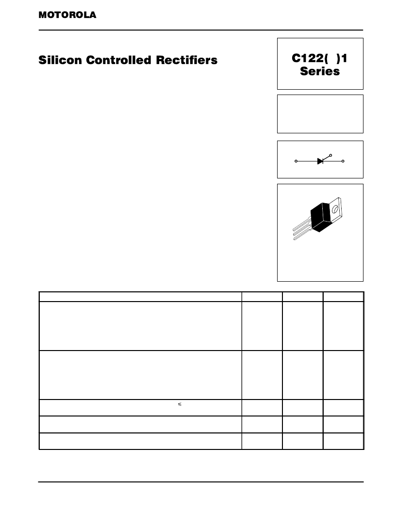
| 英文描述: | SILICON CONTROLLED RECTIFIERS |
| 中文描述: | 8 A, 600 V, SCR, TO-220AB |
| 封裝: | CASE 221A-04, 3 PIN |
| 文件頁數: | 1/3頁 |
| 文件大小: | 65K |
| 代理商: | C122M1 |
36
Motorola Thyristor Device Data
Reverse Blocking Triode Thyristors
. . . designed primarily for full-wave ac control applications, such as motor controls,
heating controls and power supplies; or wherever half-wave silicon gate-controlled,
solid-state devices are needed.
Glass Passivated Junctions and Center Gate Fire for Greater Parameter
Uniformity and Stability
Small, Rugged, Thermowatt Construction for Low Thermal Resistance, High Heat
Dissipation and Durability
Blocking Voltage to 800 Volts
Different Leadform Configurations,
Suffix (2) thru (6) available, see Leadform Options (Section 4) for Information
MAXIMUM RATINGS
(TJ = 25
°
C unless otherwise noted.)
Rating
Symbol
Value
Unit
Repetitive Peak Off-State Voltage(1) (TJ = 25 to 100
°
C, Gate Open)
Repetitive Peak Reverse Voltage
C122F1
C122A1
C122B1
C122D1
C122M1
C122N1
VDRM
VRRM
50
100
200
400
600
800
Volts
Peak Non-repetitive Reverse Voltage(1)
C122F1
C122A1
C122B1
C122D1
C122M1
C122N1
VRSM
75
200
300
500
700
800
Volts
Forward Current RMS
(All Conduction Angles)
TC
75
°
C
IT(RMS)
8
Amps
Peak Forward Surge Current
(1/2 Cycle, Sine Wave, 60 Hz)
ITSM
90
Amps
Circuit Fusing Considerations
(t = 8.3 ms)
I2t
34
A2s
1. VDRM and VRRM for all types can be applied on a continuous basis. Ratings apply for zero or negative gate voltage; however,
positive gate voltage shall not be applied concurrent with negative potential on the anode. Blocking voltages shall not be tested with a
constant current source such that the voltage ratings of the devices are exceeded.
(cont.)
SEMICONDUCTOR TECHNICAL DATA
CASE 221A-04
(TO-220AB)
STYLE 3
SCRs
8 AMPERES RMS
50 thru 800 VOLTS
K
A
G
相關PDF資料 |
PDF描述 |
|---|---|
| C122N1 | SILICON CONTROLLED RECTIFIERS |
| C1410COA | 30V N-Channel PowerTrench MOSFET |
| C1410NCUA713 | 30V N-Channel PowerTrench MOSFET |
| C1410NEOA | 30V N-Channel PowerTrench MOSFET |
| C1410NEOA713 | 30V N-Channel PowerTrench MOSFET |
相關代理商/技術參數 |
參數描述 |
|---|---|
| C122N1 | 制造商:MOTOROLA 制造商全稱:Motorola, Inc 功能描述:SILICON CONTROLLED RECTIFIERS |
| C1-22NJ-10 | 制造商:SUPERWORLD 制造商全稱:Superworld Electronics 功能描述:CERAMIC CHIP INDUCTORS |
| C123 | 制造商:Panasonic Industrial Company 功能描述:CHANGER |
| C1230 | 制造商:Thomas & Betts 功能描述:DIAPER TAPE 2 1/2 X 72 IN |
| C12-3-01-SERIES | 制造商:未知廠家 制造商全稱:未知廠家 功能描述:Interface IC |
發布緊急采購,3分鐘左右您將得到回復。