- 您現(xiàn)在的位置:買賣IC網(wǎng) > PDF目錄379724 > CA3020 (INTERSIL CORP) 8MHz Power Amps For Military, Industrial and Commercial Equipment PDF資料下載
參數(shù)資料
| 型號: | CA3020 |
| 廠商: | INTERSIL CORP |
| 元件分類: | 音頻/視頻放大 |
| 英文描述: | 8MHz Power Amps For Military, Industrial and Commercial Equipment |
| 中文描述: | 0.55 W, 1 CHANNEL, AUDIO AMPLIFIER, MBCY12 |
| 封裝: | METAL CAN-12 |
| 文件頁數(shù): | 1/9頁 |
| 文件大小: | 112K |
| 代理商: | CA3020 |
3-1
April 1997
CA3020, CA3020A
8MHz Power Amps For Military,
Industrial and Commercial Equipment
File Number
339.5
Features
High Power Output Class B Amplifier
- CA3020 . . . . . . . . . . . . . . . . . . . . 0.5W (Typ) at V
CC
= 9V
- CA3020A . . . . . . . . . . . . . . . . . . 1.0W (Typ) at V
CC
= 12V
Wide Frequency Range . . Up to 8MHz with Resistive Loads
High Power Gain. . . . . . . . . . . . . . . . . . . . . . . . . 75dB (Typ)
Single Power Supply For Class B Operation With
Transformer
- CA3020 . . . . . . . . . . . . . . . . . . . . . . . . . . . . . . . . 3V to 9V
- CA3020A . . . . . . . . . . . . . . . . . . . . . . . . . . . . . . 3V to 12V
Built-In Temperature-Tracking Voltage Regulator Provides
Stable Operation Over -55
o
C to 125
o
C Temperature Range
Applications
AF Power Amplifiers For Portable and Fixed Sound and
Communications Systems
Servo-Control Amplifiers
Wide-Band Linear Mixers
Video Power Amplifiers
Transmission-Line Driver Amplifiers (Balanced and
Unbalanced)
Fan-In and Fan-Out Amplifiers For Computer Logic Circuits
Lamp-Control Amplifiers
Motor-Control Amplifiers
Power Multivibrators
Power Switches
Description
The CA3020 and CA3020A are integrated-circuit, multi-
stage, multipurpose, wide-band power amplifiers on a single
monolithic silicon chip. They employ a highly versatile and
stable direct coupled circuit configuration featuring wide
frequency range, high voltage and power gain, and high
power output. These features plus inherent stability over a
wide temperature range make the CA3020 and CA3020A
extremely useful for a wide variety of applications in military,
industrial, and commercial equipment.
The CA3020 and CA3020A are particularly suited for service
as class B power amplifiers. The CA3020A can provide a
maximum power output of 1W from a 12V
DC
supply with a
typical power gain of 75dB. The CA3020 provides 0.5W
power output from a 9V supply with the same power gain.
Refer to AN5766 for application information.
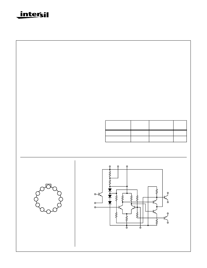
Ordering Information
PART NUMBER
TEMP.
RANGE (
o
C)
PACKAGE
PKG.
NO.
CA3020
-55 to 125
12 Pin Metal Can
T12.B
CA3020A
-55 to 125
12 Pin Metal Can
T12.B
Pinout
CA3020
(METAL CAN)
TOP VIEW
Schematic Diagram
The resistance values included on the schematic diagram have been supplied as a convenience to assist
Equipment Manufacturers in optimizing the selection of “outboard” components of equipment designs.
The values shown may vary as much as 30%.
Intersil reserves the right to make any changes in the Resistance Values provided such changes do not
adversely affect the published performance characteristics of the device.
12
1
2
3
4
11
10
9
8
7
6
5
V-
RB8
DIFF IN2
DIFF IN3
OUTPUT 4
OUTPUT 5
OUTPUT 6
OUTPUT 7
BUFFER AMP
OUT
BUFFER
AMP IN
V
CC1
RB11
Q
1
R
10
Q
2
Q
3
10
1
3
1.5K
9
8
11
R
11
1.5K
D
1
D
2
D
3
R
4
R
1
R
3
R
6
0.3K
R
9
Q
6
Q
7
Q
4
Q
5
R
5
10K
R
2
0.47K
R
5
12K
12
2
R
8
0.3K
7
6
5
4
[ /Title
(CA30
20,
CA302
0A)
/Sub-
ject
(8MHz
Power
Amps
For
Mili-
tary,
Indus-
trial
and
Com-
mer-
cial
Equip-
ment)
/Autho
r ()
/Key-
words
(Inter-
sil
Corpo-
ration,
Semi-
con-
ductor,
single,
power
ampli-
fier,
class b
ampli-
fier,
mili-
tary
CAUTION: These devices are sensitive to electrostatic discharge; follow proper IC Handling Procedures.
1-888-INTERSIL or 321-724-7143 | Copyright Intersil Corporation 1999
相關PDF資料 |
PDF描述 |
|---|---|
| CA3020A | 8MHz Power Amps For Military, Industrial and Commercial Equipment |
| CA3028AM96 | Differential/Cascode Amplifier for Commercial and Industrial Equipment from DC to 120MHz |
| CA3028A | Differential/Cascode Amplifier for Commercial and Industrial Equipment from DC to 120MHz |
| CA3028AE | Differential/Cascode Amplifier for Commercial and Industrial Equipment from DC to 120MHz |
| CA3039M96 | DIODE ZENER TRIPLE ISOLATED 200mW 12Vz 20mA-Izt 0.05 1uA-Ir 9.1 SOT-363 3K/REEL |
相關代理商/技術參數(shù) |
參數(shù)描述 |
|---|---|
| CA3020_00 | 制造商:INTERSIL 制造商全稱:Intersil Corporation 功能描述:8MHz Power Amps For Military, Industrial and Commercial Equipment |
| CA3020A | 制造商:INTERSIL 制造商全稱:Intersil Corporation 功能描述:8MHz Power Amps For Military, Industrial and Commercial Equipment |
| CA3020A3 | 制造商:未知廠家 制造商全稱:未知廠家 功能描述:Amplifier. Other |
| CA3023 | 制造商:未知廠家 制造商全稱:未知廠家 功能描述:Amplifier. Other |
| CA3026 | 制造商:未知廠家 制造商全稱:未知廠家 功能描述:High-Reliability Transistor Array Dual Independent Differential Amplifier |
發(fā)布緊急采購,3分鐘左右您將得到回復。