- 您現在的位置:買賣IC網 > PDF目錄379728 > CA3274E (INTERSIL CORP) Current Limiting Power Switch with Current Limiter Sense Flag PDF資料下載
參數資料
| 型號: | CA3274E |
| 廠商: | INTERSIL CORP |
| 元件分類: | 外設及接口 |
| 英文描述: | Current Limiting Power Switch with Current Limiter Sense Flag |
| 中文描述: | 0.2 A BUF OR INV BASED PRPHL DRVR, PDIP8 |
| 封裝: | PLASTIC, DIP-8 |
| 文件頁數: | 1/5頁 |
| 文件大小: | 27K |
| 代理商: | CA3274E |
10-40
CAUTION: These devices are sensitive to electrostatic discharge; follow proper IC Handling Procedures.
http://www.intersil.com or 407-727-9207
|
Copyright
Intersil Corporation 1999
CA3274
Current Limiting Power Switch
with Current Limiter Sense Flag
Description
The CA3274 is a controlled current switch and may be used in
general purpose switching applications that require specified
maximum levels of current. The functional block diagram of
the CA3274 is shown and a typical application circuit is shown
in Figure 1. An internal emitter follower has 200mA of source
drive output capability. The Control Input is a Schmitt trigger
buffer amplifier for noise immunity in the environments typical
of industrial and automotive control systems.
Current sensing in the emitter circuit of a power-darlington
output stage is fed back from a sampling resistor to the sense
input of the CA3274 which has a 335mV typical offset. For the
example shown in Figure 1, a sampling resistor of 0.056
permits 6.0A (0.335/0.056) of current in the emitter of the output
driver. When the current limiter is activated, the flag output
changes state conditionally. If the control input is the “0” state,
the flag output will remain in a “1” state. If the control input is in
the “1” state and the sense input is less than the voltage
reference level of 335mV, the flag output will remain in the “1”
state. If the control input is the “1” state and the sense input is
equal to or greater than the 335mV reference level, the flag
output goes to the “0” state. The output flag switch may be used
to accurately establish dwell timing in automotive applications.
When the control input goes to “0”, the flag is reset to “1”. Noise-
immunity hold-off is used to prevent pre-triggering of the flag
output and is noted as t
D
in the timing diagram of Figure 2.
The flag output may be used for diagnostic feedback via the
current sense input to detect a fault mode. In this case the
sampled drive current is either from the emitter of the CA3274
internal power transistor or an external output amplifier, such as
a darlington power transistor or power-FET output stage. The
CA3274 has separate power and signal grounds to minimize
transient-loop feedback to the input ground and thus prevent
false triggering of the output. Optionally, the output from the
CA3274 may be taken from the open collector (DRIVE IN) at
pin 6. An external resistor at pin 6 may be used to set the level
at which Q2 will saturate, providing additional limiting protection
for the maximum forward-drive from the CA3274.
Features
Drive-Current Limiting at Output
Current-Sense Buffer and Reference
200mA Driver Current Capability
Logic-Level Control Input
Current Limiting Flag Output
50dB Minimum PSRR
5
μ
s Typical Switch Time
Separate Signal and Power Grounds
Applications
Solenoid Switch Driver
Relay Driver
Lamp Control Switch
Ignition Coil Pre-Driver
Constant Current Driver
Current Limiting Switch
Fault Output Sense Appliance
Power Supply Fault Mode Control
Ordering Information
PART NUMBER
TEMPERATURE
RANGE
PACKAGE
CA3274E
-40
o
C to +85
o
C
8 Lead Plastic DIP
File Number
2222.2
April 1994
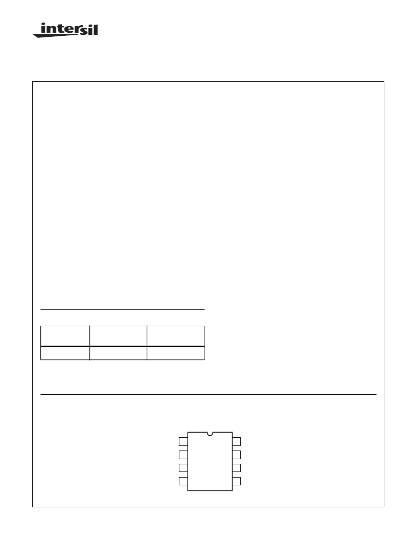
Pinout
CA3274 (PDIP)
TOP VIEW
1
2
3
4
8
7
6
5
FLAG OUT
SENSE IN
POWER GND
SIGNAL GND
CONTROL IN
DRIVE IN
DRIVE OUT
V
CC
SUPPLY
相關PDF資料 |
PDF描述 |
|---|---|
| CA3275 | Dual Full Bridge Driver(雙路滿橋驅動器) |
| CA3275E | Dual Full Bridge Driver |
| CA3277 | Dual 5V Regulator with Serial Data Buffer Interface for Microcontroller Applications(雙路5V穩壓器(帶串行數據緩沖器接口)) |
| CA3277E | Dual 5V Regulator with Serial Data Buffer Interface for Microcontroller Applications |
| CA3280 | Dual, 9MHz, Operational Transconductance Amplifier (OTA) |
相關代理商/技術參數 |
參數描述 |
|---|---|
| CA3274E WAF | 制造商:Harris Corporation 功能描述: |
| CA3275 | 制造商:INTERSIL 制造商全稱:Intersil Corporation 功能描述:Dual Full Bridge Driver |
| CA3275-000 | 制造商:TE Connectivity 功能描述:HEAT SHRNK TBING POLYFN BLCK PIECE - Bulk 制造商:TE Connectivity 功能描述:Heat Shrink Tubing ST Polyolefin Black Thin Loose Piece |
| CA3275E | 制造商:INTERSIL 制造商全稱:Intersil Corporation 功能描述:Dual Full Bridge Driver |
| CA3276 | 制造商:未知廠家 制造商全稱:未知廠家 功能描述:Analog IC |
發布緊急采購,3分鐘左右您將得到回復。