- 您現在的位置:買賣IC網 > PDF目錄374165 > CS4121ENF16 (ZF Electronics Corporation) Low Voltage Precision Air-Core Low Voltage Precision Air-Core PDF資料下載
參數資料
| 型號: | CS4121ENF16 |
| 廠商: | ZF Electronics Corporation |
| 英文描述: | Low Voltage Precision Air-Core Low Voltage Precision Air-Core |
| 中文描述: | 低電壓精密空心低電壓精密空心 |
| 文件頁數: | 1/8頁 |
| 文件大小: | 186K |
| 代理商: | CS4121ENF16 |
1
Features
SINE-
SINE+
Gnd
V
REG
F/V
OUT
SINE
Output
COS
Output
V
REG
7.0V
V
CC
COS-
COS+
Gnd
Gnd
FREQ
IN
SQ
OUT
CP+
Input
Comp.
D
+
Gnd
CP-
Voltage
Regulator
High Voltage
Protection
BIAS
Charge Pump
Func.
Gen.
D
+
+
D
+
D
+
D
+
D
I
I
I
I
I
I
Direct Sensor Input
High Torque Output
Low Pointer Flutter
High Input Impedance
Overvoltage Protection
Accurate to 8V
Functional to 6.5V (typ)
Package Options
16 Lead PDIP
(internally fused leads)
20 Lead SOIC
(internally fused leads)
C
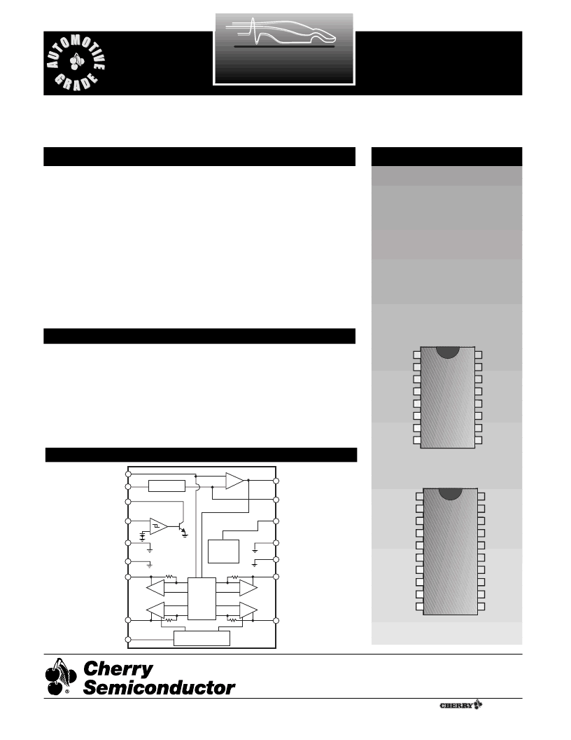
Low Voltage Precision Air-Core
Tach/Speedo Driver
Description
1
CP+
2
3
4
5
6
7
8
SQ
OUT
FREQ
IN
Gnd
Gnd
COS+
COS-
V
CC
16
15
14
13
12
11
10
9
CP-
F/V
OUT
V
REG
Gnd
Gnd
SINE+
SINE-
BIAS
1
CP+
2
3
4
5
6
7
8
SQ
OUT
FREQ
IN
Gnd
Gnd
Gnd
Gnd
COS+
16
15
14
13
12
11
10
CP-
F/V
OUT
V
REG
Gnd
Gnd
Gnd
Gnd
SIN+
9
COS-
SIN-
17
18
V
CC
BIAS
19
20
CS4121
The CS4121 is specifically designed
for use with air-core meter move-
ments. The IC provides all the func-
tions necessary for an analog
tachometer or speedometer. The
CS4121 takes a speed sensor input
and generates sine and cosine relat-
ed output signals to differentially
drive an air-core meter.
Many enhancements have been
added over industry standard
tachometer drivers such as the
CS289 or LM1819. The output uti-
lizes differential drivers which elim-
inates the need for a zener reference
and offers more torque. The device
withstands 60V transients which
decreases the protection circuitry
required. The device is also more
precise than existing devices allow-
ing for fewer trims and for use in a
speedometer.
The CS4121 is compatible with the
CS8190, and provides higher accu-
racy at a lower supply voltage (8.0V
min. as opposed to 8.5V). It is func-
tionally operational to 6.5V.
Block Diagram
Absolute Maximum Ratings
Supply Voltage (<100ms pulse transient)..........................................V
CC
= 60V
(continuous)..............................................................V
CC
= 24V
Operating Temperature.............................................................D40C to +105C
Storage Temperature..................................................................D40C to +165C
Junction Temperature.................................................................D40C to+150C
ESD (Human Body Model).............................................................................4kV
Lead Temperature Soldering
Wave Solder (through hole styles only)............10 sec. max, 260C peak
Reflow (SMD styles only).............60 sec. max above 183C, 230C peak
Cherry Semiconductor Corporation
2000 South County Trail, East Greenwich, RI 02818
Tel: (401)885-3600 Fax: (401)885-5786
Email: info@cherry-semi.com
Web Site: www.cherry-semi.com
A
Company
¨
Rev 12/4/96
相關PDF資料 |
PDF描述 |
|---|---|
| CS4121EDWFR20 | Low Voltage Precision Air-Core Low Voltage Precision Air-Core |
| CS4121EDWF20 | Low Voltage Precision Air-Core Low Voltage Precision Air-Core |
| CS4121 | Low Voltage Precision Air-Core Low Voltage Precision Air-Core |
| CS4124YN16 | CAT 7 PLENUM BLUE BULK CABLE |
| CS4124 | High Side PWM FET Controller |
相關代理商/技術參數 |
參數描述 |
|---|---|
| CS4121ENF16G | 功能描述:馬達/運動/點火控制器和驅動器 Low Voltage Air-Core Tach/Speedo Driver RoHS:否 制造商:STMicroelectronics 產品:Stepper Motor Controllers / Drivers 類型:2 Phase Stepper Motor Driver 工作電源電壓:8 V to 45 V 電源電流:0.5 mA 工作溫度:- 25 C to + 125 C 安裝風格:SMD/SMT 封裝 / 箱體:HTSSOP-28 封裝:Tube |
| CS4121N16 | 制造商:ON Semiconductor 功能描述: |
| CS-4121N16 | 制造商:未知廠家 制造商全稱:未知廠家 功能描述:Tachometer Circuit |
| CS4122 | 制造商:ONSEMI 制造商全稱:ON Semiconductor 功能描述:Triple Air−Core Gauge Driver with Serial Input Bus |
| CS4122/D | 制造商:未知廠家 制造商全稱:未知廠家 功能描述:Triple Air-Core Gauge Driver with Serial Bus Input |
發布緊急采購,3分鐘左右您將得到回復。