- 您現在的位置:買賣IC網 > PDF目錄376987 > DS9-12F (IXYS CORP) Rectifier Diode Avalanche Diode PDF資料下載
參數資料
| 型號: | DS9-12F |
| 廠商: | IXYS CORP |
| 元件分類: | 參考電壓二極管 |
| 英文描述: | Rectifier Diode Avalanche Diode |
| 中文描述: | 11 A, 1200 V, SILICON, RECTIFIER DIODE, DO-203AA |
| 封裝: | DO-4, 1 PIN |
| 文件頁數: | 1/2頁 |
| 文件大小: | 46K |
| 代理商: | DS9-12F |
2000 IXYS All rights reserved
1 - 2
V
RSM
V
900
1300
1700
1900
V
(BR)min
x
V
RRM
V
Standard
Types
DS
9-08F
DS
9-12F
Avalanche
Types
V
800
1200
1600
1800
1300
1750
1950
DSA
9-12F
DSA
9-16F
DSA
9-18F
x
Only for Avalanche Diodes
Symbol
Test Conditions
Maximum Ratings
I
F(RMS)
I
F(AVM)
P
RSM
I
FSM
T
VJ
T
case
= 150 C; 180 sine
DSA types, T
VJ
= T
VJM
, t
p
= 10 s
T
VJ
= 45 C;
V
R
= 0
T
VJ
= T
VJM
V
R
= 0
T
VJ
= 45 C
V
R
= 0
T
VJ
= T
VJM
V
R
= 0
= T
18
11
A
A
4.5
kW
t = 10 ms (50 Hz), sine
t = 8.3 ms (60 Hz), sine
t = 10 ms (50 Hz), sine
t = 8.3 ms (60 Hz), sine
250
265
200
220
A
A
A
A
I
2
t
t = 10 ms (50 Hz), sine
t = 8.3 ms (60 Hz), sine
t = 10 ms (50 Hz), sine
t = 8.3 ms (60 Hz), sine
310
295
200
190
A
2
s
A
2
s
A
2
s
A
2
s
T
VJ
T
VJM
T
stg
M
d
-40...+180
C
C
C
180
-40...+180
Mounting torque
2.2-2.8
19-25
Nm
lb.in.
g
Weight
5
V
RRM
= 800-1800 V
I
F(RMS)
= 18 A
I
F(AV)M
= 11 A
Features
G
International standard package,
JEDEC DO-203 AA
G
Planar glassivated chips
Applications
G
Supplies for DC power equipment
G
DC supply for PWM inverter
G
Field supply for DC motors
G
Battery DC power supplies
Advantages
G
Space and weight savings
G
Simple mounting
G
Improved temperature and power
cycling
G
Reduced protection circuits
Symbol
Test Conditions
Characteristic Values
I
R
V
F
V
T0
r
T
R
thJC
T
VJ
I
F
For power-loss calculations only
T
VJ
= T
VJM
DC current
180 sine
DC current
= T
VJM
; V
R
= V
RRM
= 36 A; T
VJ
= 25 C
3
mA
1.4
V
0.85
15
V
m
2.0
2.17
3.0
K/W
K/W
K/W
R
thJH
d
S
d
A
a
Creepage distance on surface
Strike distance through air
Max. allowable acceleration
2.0
2.0
100
mm
mm
m/s
2
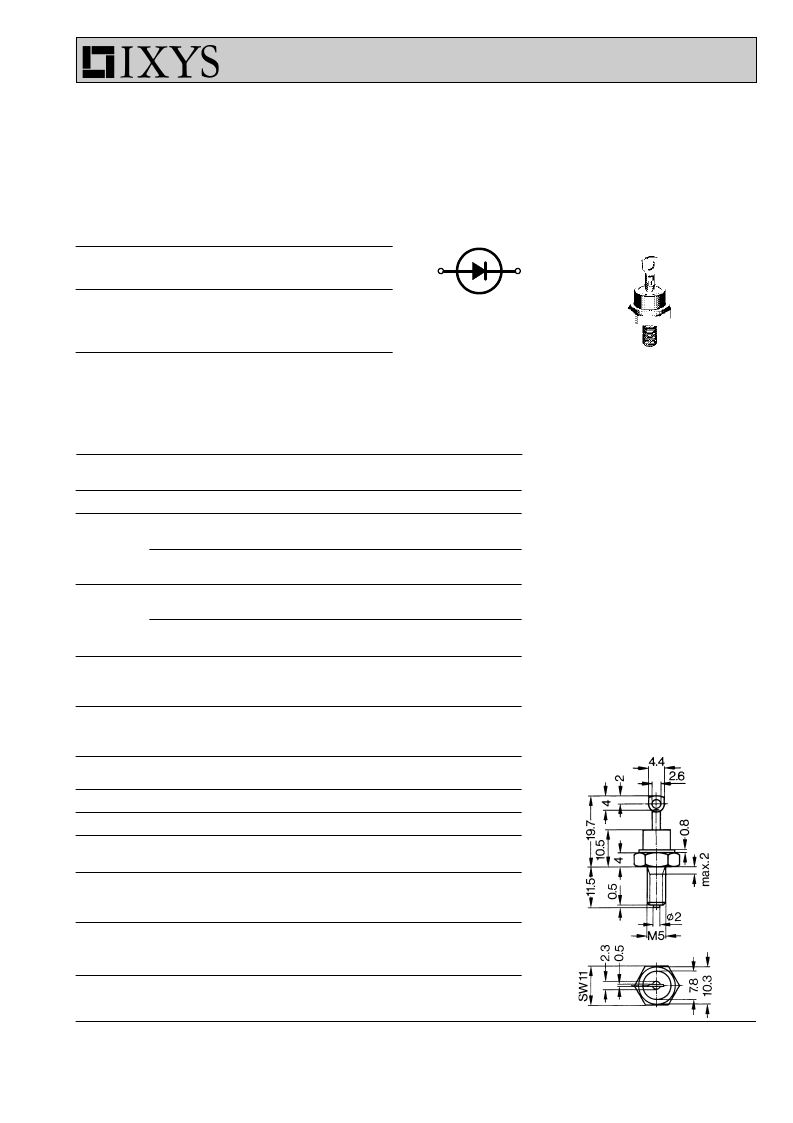
Dimensions in mm (1 mm = 0.0394")
Data according to IEC 60747
IXYS reserves the right to change limits, test conditions and dimensions
DS
DSA 9
9
Rectifier Diode
Avalanche Diode
A
C
DO-203 AA
A = Anode C = Cathode
C
A
M5
相關PDF資料 |
PDF描述 |
|---|---|
| DSA9-16F | Rectifier Diode Avalanche Diode |
| DSA9-18F | Rectifier Diode Avalanche Diode |
| DSB0.5A20 | Schottky Barrier Rectifiers(肖特基勢壘整流二極管) |
| DSB02A30 | DIODE SWITCHING 80V 100MA 1005 |
| DSB05A20 | 0.2 AND 0.5 AMP SCHOTTKY BARRIER RECTIFIERS |
相關代理商/技術參數 |
參數描述 |
|---|---|
| DS9194 | 制造商:未知廠家 制造商全稱:未知廠家 功能描述: |
| DS9194-05P | 制造商:未知廠家 制造商全稱:未知廠家 功能描述: |
| DS91982 | 制造商:Rochester Electronics LLC 功能描述:- Bulk |
| DS91983 | 制造商:Rochester Electronics LLC 功能描述:- Bulk |
| DS91C176 | 制造商:NSC 制造商全稱:National Semiconductor 功能描述:100 MHz Single Channel M-LVDS Transceivers |
發布緊急采購,3分鐘左右您將得到回復。