- 您現在的位置:買賣IC網 > PDF目錄375715 > FA5311 (FUJI ELECTRIC HOLDINGS CO., LTD.) CAP 100PF 50V 5% C0G SMD-0603 TR-7-PA SN100 PDF資料下載
參數資料
| 型號: | FA5311 |
| 廠商: | FUJI ELECTRIC HOLDINGS CO., LTD. |
| 英文描述: | CAP 100PF 50V 5% C0G SMD-0603 TR-7-PA SN100 |
| 中文描述: | 雙極集成電路開關電源控制 |
| 文件頁數: | 4/17頁 |
| 文件大小: | 263K |
| 代理商: | FA5311 |
4
FA531X series
I
Description of each circuit
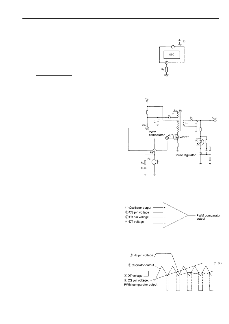
1. Oscillator
(See block diagram)
The oscillator generates a triangular waveform by charging and
discharging a capacitor. CT pin voltage oscillates
between an upper limit of approx. 3.0V and a lower limit of
approx. 1.0V. The oscillation frequency is determined by a
external resistance and capacitance shown in figure 1, and
approximately given by the following equation:
The recommended oscillation range is between 5k and
600kHz.
The oscillator output is connected to a PWM comparator.
2. Feedback pin circuit
Figure 2 gives an example of connection in which an
optocoupler is used to couple the feedback signal to the FB pin.
It is designed to be strong against noise and will not create
parasitic oscillation so much, because the output impedance at
the FB pin is as low as 4k to 5k. If this circuit causes power
supply instability, the frequency gain can be decreased by
connecting R
4
and C
4
as shown in figure 2. R
4
should be
between several tens of ohms to several kiloohms and C
4
should be between several thousand picofarads to one
microfarads.
3. PWM comparator
The PWM comparator has four inputs as shown in Figure 3.
Oscillator output
x
is compared with CS pin voltage
, FB pin
voltage
, and DT voltage
{
. The lowest of three inputs
,
,
and
{
is compared with output
x
. If it is lower than the
oscillator output, the PWM comparator output is high, and if it is
higher than the oscillator output, the PWM comparator
output is low (see Fig. 4).
The IC output voltage is high during when the comparator
output is low, and the IC output voltage is low during when the
comparator output is high.
When the IC is powered up, CS pin voltage
controls soft start
operation. The output pulse then begins to widen gradually.
During normal operation, the output pulse width is determined
within the maximum duty cycle set by DT voltage
{
under the
condition set by feedback signal
, to stabilize the output
voltage.
f (kH
Z
) =
10
6
.........(1)
Fig. 1 Oscillator
Fig. 2 Configuration with optocoupler (FB pin input)
Fig. 3 PWM comparator
Fig. 4 PWM comparator timing chart
4R
T
(k
) C
T
(pF)
相關PDF資料 |
PDF描述 |
|---|---|
| FA5311BP | Bipolar IC For Switching Power Supply Control |
| FA5311BPS | Bipolar IC For Switching Power Supply Control |
| FA5314PS | Bipolar IC For Switching Power Supply Control |
| FA5315P | Bipolar IC For Switching Power Supply Control |
| FA5315PS | Bipolar IC For Switching Power Supply Control |
相關代理商/技術參數 |
參數描述 |
|---|---|
| FA5311BP | 制造商:FUJI 制造商全稱:Fuji Electric 功能描述:Bipolar IC For Switching Power Supply Control |
| FA5311BP(S) | 制造商:未知廠家 制造商全稱:未知廠家 功能描述: |
| FA5311BPS | 制造商:FUJI 制造商全稱:Fuji Electric 功能描述:Bipolar IC For Switching Power Supply Control |
| FA5311BS | 制造商:未知廠家 制造商全稱:未知廠家 功能描述:(374.50 k) |
| FA5311P | 制造商:Panasonic Industrial Company 功能描述:IC |
發布緊急采購,3分鐘左右您將得到回復。