- 您現在的位置:買賣IC網 > PDF目錄375715 > FA5331M (FUJI ELECTRIC CO LTD) Bipolar IC For Power Factor Correction PDF資料下載
參數資料
| 型號: | FA5331M |
| 廠商: | FUJI ELECTRIC CO LTD |
| 元件分類: | 穩壓器 |
| 英文描述: | Bipolar IC For Power Factor Correction |
| 中文描述: | 1.5 A POWER FACTOR CONTROLLER, 220 kHz SWITCHING FREQ-MAX, PDSO16 |
| 封裝: | PLASTIC, SOP-16 |
| 文件頁數: | 8/13頁 |
| 文件大小: | 151K |
| 代理商: | FA5331M |
8
FA5331P(M)/FA5332P(M)
I
Design advice
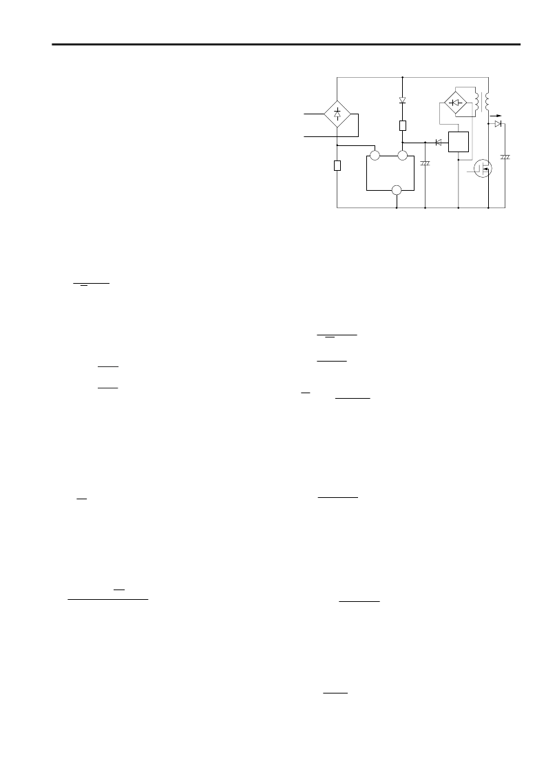
1. Start circuit
Figure 9 shows a sample start circuit. Since the IC current
while the Vcc pin voltage rises from 0V to V
THON
is as small as
90
μ
A (typ.), the power loss in resistor R
A
is small. If an
additional winding is prepared in the voltage step-up inductor
(L), power to the control circuit can be supplied from this
circuit. However, the voltage must be stabilized by a regulator
circuit (REG) to prevent an excess rise of the IC supply voltage
(Vcc). Use fast or ultra-fast rectifier diodes for the rectifier circuit
(DB1) of the winding for high-frequency operation.
2. Current sensing resistor
The current sensing resistor (Rs) detects the current in the
inductor. Rs is used to make the input current sinusoidal. The
current in the inductor produces a negative voltage across Rs.
The voltage is input to IC pin 16 (IDET). Determine the value
of Rs so that the peak voltage of the IDET pin is –1V.
Rs =
Vin
√
2 Pin
..................................................(11)
Vin: Minimum AC input voltage (effective value) [V]
Pin: Maximum input power [W]
Since the threshold voltage of the overcurrent limiting circuit
(pin 16) is –1.15V for FA5311 for and –1.10V for FA5332, the
peak input current limit (ip) is determined by:
FA5332: ip=1.10
Rs
3. Voltage step-up type converter
Figure 9 shows the basic circuit of a voltage step-up type
converter which is used as a power factor correction.
(a) Output voltage
For stable operation, set the output voltage to be 10V or more
over the peak value of the maximum input voltage. When
using this IC for an active filter, set the output voltage (Vo) as
follows:
Vo
≥ √
2 Vin + 10V
............................................(13)
Vin: Maximum AC input voltage [V]
(effective value of sinusoidal wave)
(b) Voltage step-up inductor
When using a voltage step-up converter in continuous current
mode, the ratio of inductor current ripple to the input peak
current is set to about 20%. Determine the inductance as
follows:
L
≥
Vin
2
( Vo –
√
2 Vin )
γ
fs Pin Vo
Vin: Minimum AC input voltage (effective value) [V]
γ
:
Ratio of inductor current ripple (peak to peak value) to the
input peak current (about 0.2)
fs:
Switching frequency [Hz]
Pin: Converter’s maximum input power [W]
As the characteristic curves on page 66 show, the peak
voltage at pin 3 should be at least 0.65V, even when the AC
input voltage is minimal. Considering this, determine R6 and
R7 shown in Fig. 6.
................................(14)
Fig. 9 Start circuit
Example: FA5332
When Vin is 85V and Pin is 300W, the formulas of (11)
and (12) can be calculated as:
Rs =
85
√
2 300
= 0.2 [
]
ip =
1.10
0.2
= 5.5 [ A ]
√
2 85
R6
R6 + R7
= 0.65 [ V ]
And,
If R6 is set to 2.7k
to satisfy these formulas, R7 becomes
480k
.
Example:
When Vin is 85V, Vo is 385V, and
γ
is 0.2, the formula of (14)
can be calculated as:
L
≥
2.48
10
4
fs Pin
[ H ]
.........................................(15)
(c) Smoothing capacitor
When a voltage step-up converter is used in a power factor
correction circuit, the input current waveform is regulated to be
in-phase with the input voltage waveform. Therefore, ripple
noise of twice the input line frequency appears at the output.
The output voltage (
υ
o
) is represented as:
υ
o
= Vo –
Io
2
ω
o
C
Sin 2
ω
o
t
...................(16)
Vo:Average output voltage
Io: Output current
ω
o
: 2
π
fo (fo: Input power frequency, 50 or 60Hz)
C: Smoothing capacitor value
Therefore, the peak-to-peak value of the output ripple voltage
Vrp is given by:
Vrp =
Io
ω
o
C
..................................................... (17)
Using formula (17), determine the necessary C value.
16
10
7
C
A
R
A
R
S
Vcc
AC input
DB1
L
REG
C
FA5331/FA5332
Io
....................1.15
相關PDF資料 |
PDF描述 |
|---|---|
| FA5332M | Bipolar IC For Power Factor Correction |
| FA5332P | Bipolar IC For Power Factor Correction |
| FA5332PM | Bipolar IC For Power Factor Correction |
| FA5502 | POWER SUPPLY CONTROL IC |
| FA5530 | Quasi-Resonant IC |
相關代理商/技術參數 |
參數描述 |
|---|---|
| FA5331P | 制造商:Panasonic Industrial Company 功能描述:IC |
| FA5331P(M) | 制造商:未知廠家 制造商全稱:未知廠家 功能描述:FA5331P(M) and FA5332P(M) are control ICs for a power factor correction system. |
| FA5331PM | 制造商:FUJI 制造商全稱:Fuji Electric 功能描述:Bipolar IC For Power Factor Correction |
| FA5332M | 制造商:FUJI 制造商全稱:Fuji Electric 功能描述:Bipolar IC For Power Factor Correction |
| FA5332P | 制造商:FUJI 制造商全稱:Fuji Electric 功能描述:Bipolar IC For Power Factor Correction |
發布緊急采購,3分鐘左右您將得到回復。