- 您現在的位置:買賣IC網 > Datasheet目錄38 > FAN4800AUN (Fairchild Semiconductor)IC PWM/PFC CTLR COMBO 16-MDIP Datasheet資料下載
參數資料
| 型號: | FAN4800AUN |
| 廠商: | Fairchild Semiconductor |
| 文件頁數: | 14/19頁 |
| 文件大小: | 1414K |
| 描述: | IC PWM/PFC CTLR COMBO 16-MDIP |
| 標準包裝: | 1,800 |
| 模式: | 平均電流 |
| 頻率 - 開關: | 240kHz ~ 268kHz |
| 電流 - 啟動: | 30µA |
| 電源電壓: | 11 V ~ 22 V |
| 工作溫度: | -40°C ~ 105°C |
| 安裝類型: | 通孔 |
| 封裝/外殼: | 16-DIP(0.300",7.62mm) |
| 供應商設備封裝: | 16-MDIP |
| 包裝: | 管件 |
?2011 Fairchild Semiconductor Corporation
www.fairchildsemi.com
FAN4800AU/CU " Rev. 1.0.1
14
V
RM S
V
R M S -U V P
2
1
R
M
S
V
?/DIV>
7.94
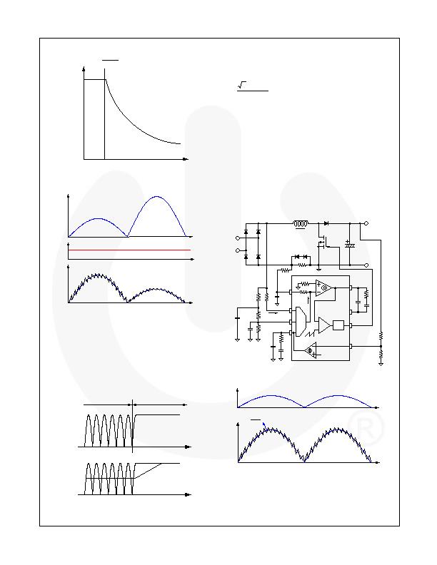
Figure 29. Modulation Gain Characteristics
V
IN
I
L
V
E A
Figure 30. Line Feed-Forward Operation
To sense the RMS value of the line voltage, averaging
circuit with two poles is typically employed, as shown in
Figure 28. Notice that the input voltage of the PFC is
clamped at the peak of the line voltage once the PFC
stops switching because the junction capacitance of the
bridge diode is not discharged, as shown in Figure 31.
Therefore, the voltage divider for VRMS should be
designed considering the brownout protection trip-point
and minimum operation line voltage.
PFC Runs
PFC Stops
V
IN
V
RMS
Figure 31. V
RMS
According to the PFC Operation
The rectified sinusoidal signal is obtained by the current
flowing into the IAC pin. The resistor R
IAC
should be
large enough to prevent saturation of the gain
modulator, calculating as:
A
G
R
V
M A X
IA
M IN
LINE
m
140
2
<
?/DIV>
主站蜘蛛池模板:
林周县|
怀宁县|
随州市|
黔西|
宜黄县|
秦安县|
云南省|
金山区|
安溪县|
汾阳市|
阿巴嘎旗|
和林格尔县|
唐河县|
迁西县|
久治县|
三门峡市|
沂源县|
乐亭县|
昆山市|
平武县|
观塘区|
商河县|
屏边|
龙胜|
黄石市|
博爱县|
威宁|
岐山县|
富蕴县|
海城市|
宁河县|
措勤县|
泽库县|
墨竹工卡县|
慈利县|
分宜县|
句容市|
鄂尔多斯市|
巴彦淖尔市|
山阳县|
永安市|
(3)
where V
LINEMIN
is the line voltage that trips brownout
protection, G
MAX
is the maximum modulator gain
when V
RMS
is 1.08 V (which can be found in the
datasheet), and 140 礎 is the maximum output
current of the gain modulator.
Current Control of Boost Stage
The FAN4800AU/CU employs two control loops for
power factor correction, as shown in Figure 32: a
current-control loop and a voltage-control loop. The
current-control loop shapes inductor current as shown
in Figure 33 based on the reference signal obtained at
the IAC pin calculated as:
M
A
M
M
L
R
G
I
R
I
R
?/DIV>
?/DIV>
=
?/DIV>
=
?/DIV>
1
(4)
IS E N S E
IA C
V R M S
V E A
IE A
R
M
R M
R
R M S 1
R
R M S 2
R R M S 3
C
R M S 1
C R M S 2
R I A C
I
A C
V
I N
I
L
R
C S 1
R
F 1
C
F 1
I M O
R
I C
C I C 1
C
I C 2
+
-
D riv e
lo g ic
O P F C
2 .5 V
R
V C
R
V C 1
R
V C 2
F B P F C
R
F B 1
R
F B 2
V
O
V R E F
Figure 32. Gain Modulation Block
I
A C
I
L
M
M
O
R
R
Figure 33. Inductor Current Shaping
The current-control feedback loop also has a pulse-by-
pulse current limit comparator that forces the PFC
switch to turn off until the next switching cycle if the
ISENSE pin voltage drops below -1.3 V.
相關PDF資料 |
PDF描述 |
|---|---|
| FAN4800CUN | IC PWM/PFC CTLR COMBO 16-MDIP |
| FAN4802MY | IC PFC CTRLR AVERAGE CURR 16SOP |
| FAN4802SNY | IC CTLR PFC/PWM COMBO 16-PDIP |
| FAN6920MRMY | IC PWM CTLR PFC/QUASI-RES 16SOP |
| FAN6921MLMY | IC CTLR PFC/FLYBACK 16-SOICN |
相關代理商/技術參數 |
參數描述 |
|---|---|
| FAN4800C | 制造商:FAIRCHILD 制造商全稱:Fairchild Semiconductor 功能描述:PFC/PWM Controller Combination |
| FAN4800CMY | 功能描述:電流型 PWM 控制器 PWM/PFC, Avg Curr 30uA SU, 2.6mA Op RoHS:否 制造商:Texas Instruments 開關頻率:27 KHz 上升時間: 下降時間: 工作電源電壓:6 V to 15 V 工作電源電流:1.5 mA 輸出端數量:1 最大工作溫度:+ 105 C 安裝風格:SMD/SMT 封裝 / 箱體:TSSOP-14 |
| FAN4800CNY | 功能描述:電流型 PWM 控制器 PWM/PFC, Avg Curr 30uA SU, 2.6mA Op RoHS:否 制造商:Texas Instruments 開關頻率:27 KHz 上升時間: 下降時間: 工作電源電壓:6 V to 15 V 工作電源電流:1.5 mA 輸出端數量:1 最大工作溫度:+ 105 C 安裝風格:SMD/SMT 封裝 / 箱體:TSSOP-14 |
| FAN4800CS | 制造商:FAIRCHILD 制造商全稱:Fairchild Semiconductor 功能描述:PFC/PWM Controller Combination |
| FAN4800CSMY | 功能描述:電流型 PWM 控制器 PFC/PWM Controller Combination RoHS:否 制造商:Texas Instruments 開關頻率:27 KHz 上升時間: 下降時間: 工作電源電壓:6 V to 15 V 工作電源電流:1.5 mA 輸出端數量:1 最大工作溫度:+ 105 C 安裝風格:SMD/SMT 封裝 / 箱體:TSSOP-14 |
發布緊急采購,3分鐘左右您將得到回復。