- 您現在的位置:買賣IC網 > PDF目錄375797 > FIC03272 (Electronic Theatre Controls, Inc.) Microprocessor for handling signals from the TGS4161 carbon dioxide sensor PDF資料下載
參數資料
| 型號: | FIC03272 |
| 廠商: | Electronic Theatre Controls, Inc. |
| 英文描述: | Microprocessor for handling signals from the TGS4161 carbon dioxide sensor |
| 中文描述: | 微處理器處理的TGS4161二氧化碳傳感器信號 |
| 文件頁數: | 9/14頁 |
| 文件大小: | 366K |
| 代理商: | FIC03272 |
Revised 06/04
9
TECHNICAL INFORMATION FOR FIC03272
Analog output (0~3V)
for CO
2
concentration
R91
FIC03272
1M
10k
10
μ
LM324N
6.2V
100
1M
22k
1
2
3
25
5-3
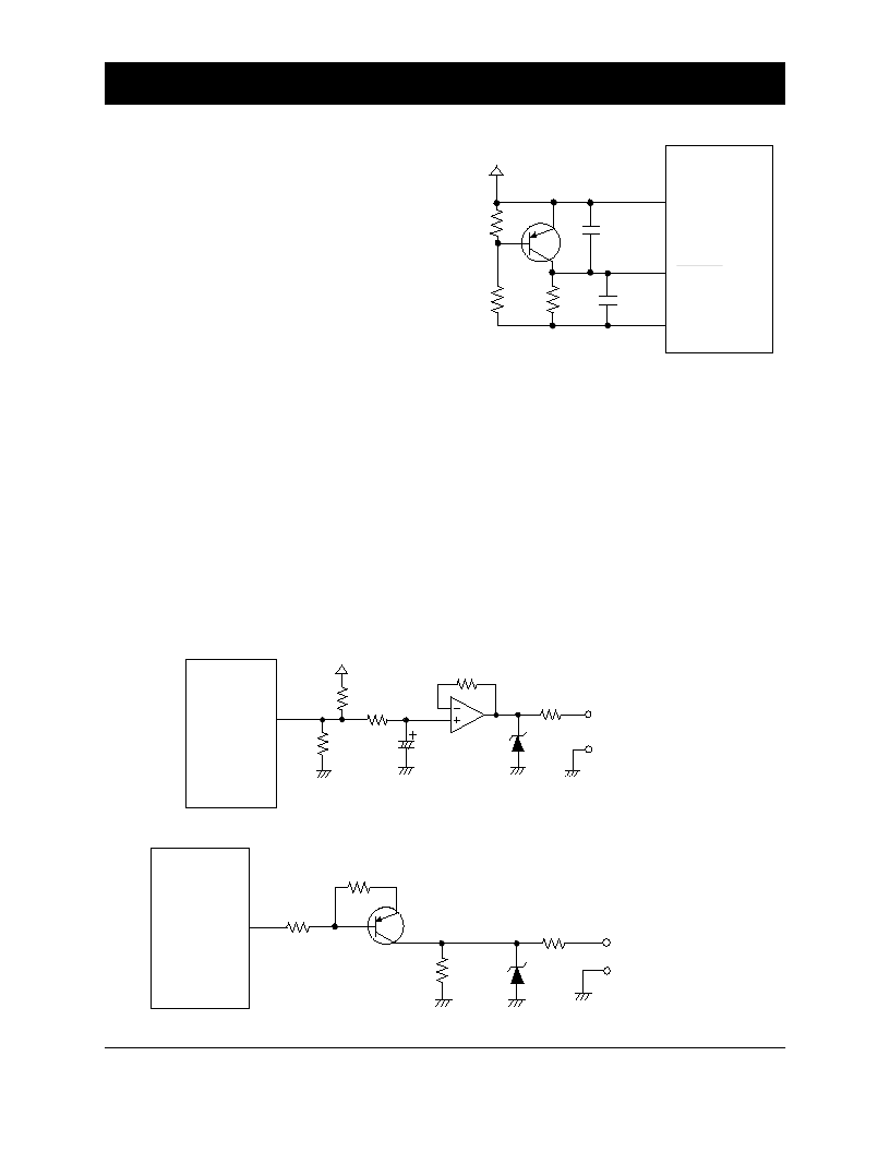
System reset circuit
Under normal operating conditions, an “H” signal is
continuously applied to the RESET port (Pin #3).
When an “L” signal is applied to the RESET port for
a period of one machine cycle or longer, the internal
logic circuit of FIC03272 and the micro-processor’s
program return to the same condition which exists
just after powering on the unit, effectively resetting
the system.
To perform the above described system reset function
automatically, a circuit such as that shown in Figure
6 is suggested. This kind of automatic system reset
circuit is useful in circumstances such as just after
powering on, after a momentary power interruption,
at the moment of recovery after a sudden drop of
voltage, etc. The microprocessor’s program some-
times does not run correctly in these cases due to a
malfunction of the internal logic circuit in the
processor. Manual resets help to assure normal
operation of the microprocessor’s program.
5-4
CO
2
concentration signal circuit
Port 91 (Pin No. 25) outputs a PWM signal which
represents a CO
2
concentration in the range between
400 and 3000ppm. Figure 7 illustrates a sample circuit
for converting a PWM signal to a linear output of 0~3V
DC. A delay of several seconds is anticipated in the
DC voltage concentration signal because a C-R
combination is used in the circuit. A 100
resistor is
connected in series to protect the external circuit from
excessive current.
5-5
Circuit for damper control signal
Figure 8 shows an example circuit in which an H/L
signal which is output from port R60 (Pin No. 16)
and converted to an On/Off signal for controlling
the opening/closing of a damper. A 100
resistor is
connected in series to protect the external circuit from
excessive current.
Figure 6 - Reset circuit
Figure 7 - CO
2
concentration signal circuit
1k
3.9k
4. 7k
103
2SA1015Y
104
14
28
3
+4.4V
FIC03272
V
DD
V
SS
RESET
16
10k
6. 2V
100
2SA1015Y
1k
10k
FIC03272
Damper control signal
R60
Figure 8 - Damper control circuit
相關PDF資料 |
PDF描述 |
|---|---|
| FID-550 | Resistive Touch Panel Specification |
| FID3Z1KX | 320 x 240 pixel format, LED or CFL Backlight |
| FID3Z1LX | 320 x 240 pixel format, LED or CFL Backlight |
| FID3Z2KX | 122 x 32 pixel format, Compact LCD size |
| FID3Z2LX | 122 x 32 pixel format, Compact LCD size |
相關代理商/技術參數 |
參數描述 |
|---|---|
| FIC04G-60 | 制造商:AXIOMTEK 制造商全稱:AXIOMTEK 功能描述:Anti-vibration & shock resistance |
| FIC08G-60 | 制造商:AXIOMTEK 制造商全稱:AXIOMTEK 功能描述:Anti-vibration & shock resistance |
| FIC128-60 | 制造商:AXIOMTEK 制造商全稱:AXIOMTEK 功能描述:Anti-vibration & shock resistance |
| FIC16G-60 | 制造商:AXIOMTEK 制造商全稱:AXIOMTEK 功能描述:Anti-vibration & shock resistance |
| FIC-200 | 功能描述:安全/ 驗證開發工具 PC Card Type II Fingerprint Reader RoHS:否 制造商:Digi International 產品:Development Kits 工具用于評估:XEB-AW140 接口類型:SPI, USB 工作電源電壓:3.1 V to 3.6 V |
發布緊急采購,3分鐘左右您將得到回復。