- 您現在的位置:買賣IC網 > PDF目錄375798 > FIN1028 (Fairchild Semiconductor Corporation) 3.3V LVDS 2-Bit High Speed Differential Receiver PDF資料下載
參數資料
| 型號: | FIN1028 |
| 廠商: | Fairchild Semiconductor Corporation |
| 英文描述: | 3.3V LVDS 2-Bit High Speed Differential Receiver |
| 中文描述: | 3.3 LVDS的2位高速差分接收器 |
| 文件頁數: | 2/9頁 |
| 文件大小: | 1027K |
| 代理商: | FIN1028 |
www.fairchildsemi.com
2
F
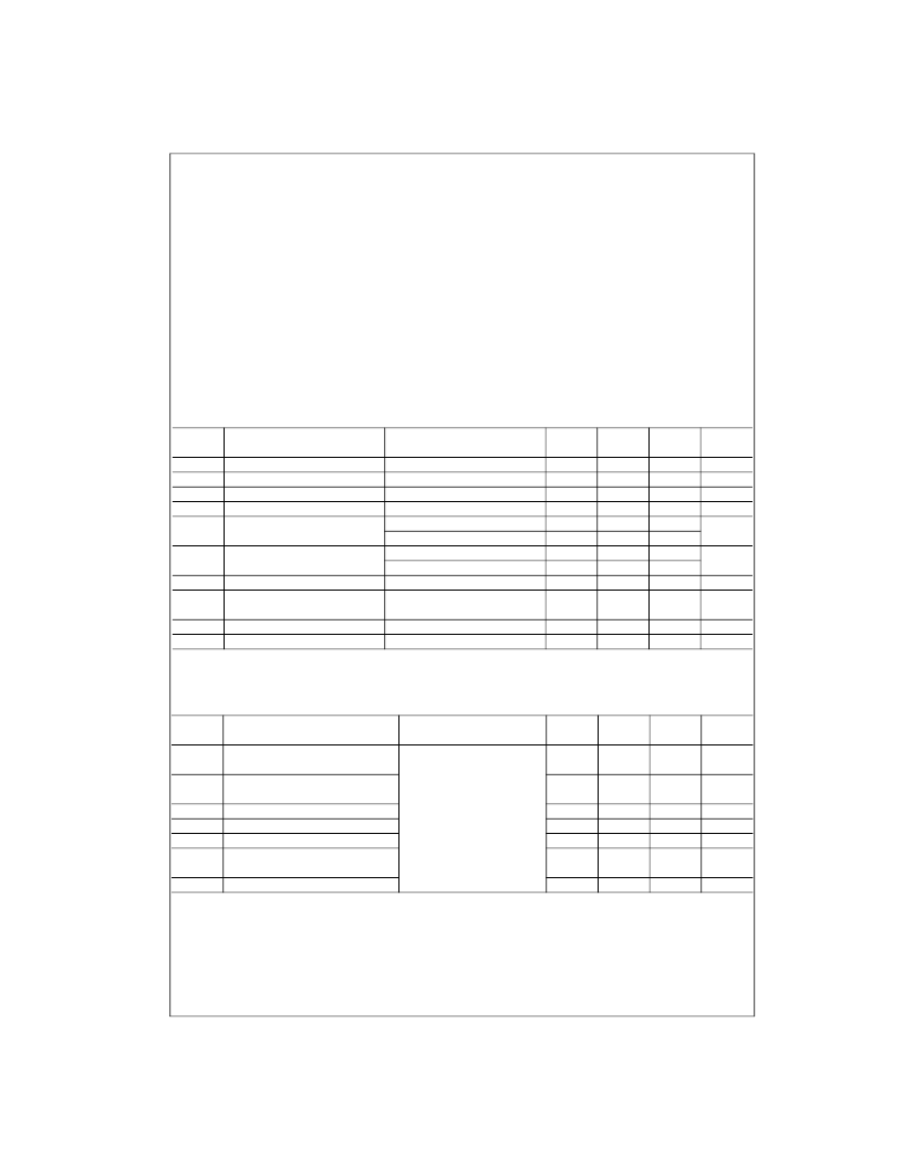
Absolute Maximum Ratings
(Note 2)
Recommended Operating
Conditions
Note 2:
The
“
Absolute Maximum Ratings
”
: are those values beyond which
damage to the device may occur. The databook specifications should be
met, without exception, to ensure that the system design is reliable over its
power supply, temperature and output/input loading variables. Fairchild
does not recommend operation of circuits outside databook specification.
DC Electrical Characteristics
Over supply voltage and operating temperature ranges, unless otherwise specified
Note 3:
All typical values are at T
A
=
25
°
C and with V
CC
=
3.3V.
AC Electrical Characteristics
Over supply voltage and operating temperature ranges, unless otherwise specified
Note 4:
All typical values are at T
A
=
25
°
C and with V
CC
=
3.3V.
Note 5:
t
SK(LH)
, t
SK(HL)
is the skew between specified outputs of a single device when the outputs have identical loads and are switching in the same direc-
tion.
Note 6:
t
SK(PP)
is the magnitude of the difference in propagation delay times between any specified terminals of two devices switching in the same direction
(either LOW-to-HIGH or HIGH-to-LOW) when both devices operate with the same supply voltage, same temperature, and have identical test circuits.
Supply Voltage (V
CC
)
DC Input Voltage (R
INx
+
, R
INx
)
DC Output Voltage (R
OUTx
)
DC Output Current (I
O
)
Storage Temperature Range (T
STG
)
Max Junction Temperature (T
J
)
Lead Temperature (T
L
)
(Soldering, 10 seconds)
ESD (Human Body Model)
ESD (Machine Model)
0.5V to
+
4.6V
0.5V to
+
4.7V
0.5V to
+
6V
16 mA
65
°
C to
+
150
°
C
150
°
C
260
°
C
≥
6500V
≥
300V
Supply Voltage (V
CC
)
Input Voltage (V
IN
)
Magnitude of Differential Voltage
(|V
ID
|)
Common-mode Input Voltage
(V
IC
)
Operating Temperature (T
A
)
3.0V to 3.6V
0 to V
CC
100 mV to V
CC
0.05V to 2.35V
40
°
C to
+
85
°
C
Symbol
Parameter
Test Conditions
Min
Typ
Max
Units
(Note 3)
V
TH
V
TL
I
IN
I
I(OFF)
V
OH
Differential Input Threshold HIGH
See Figure 1 and Table 1
100
mV
Differential Input Threshold LOW
Input Current
Power-OFF Input Current
See Figure 1 and Table 1
V
IN
=
0V or V
CC
V
CC
=
0V, V
IN
=
0V or 3.6V
I
OH
=
100
μ
A
I
OH
=
8 mA
I
OH
=
100
μ
A
I
OL
=
8 mA
I
IK
=
18 mA
(R
IN
+
=
1V and R
IN
=
1.4V) or
(R
IN
+
=
1.4V and R
IN
=
1V)
100
mV
μ
A
μ
A
±
20
±
20
Output HIGH Voltage
V
CC
0.2
2.4
V
V
OL
Output LOW Voltage
0.2
V
0.5
V
IK
I
CC
Input Clamp Voltage
Power Supply Current
1.5
V
9
mA
C
IN
C
OUT
Input Capacitance
Output Capacitance
4
6
pF
pF
Symbol
Parameter
Test Conditions
Min
Typ
Max
Units
(Note 4)
t
PLH
Differential Propagation Delay
0.9
2.5
ns
LOW-to-HIGH
Differential Propagation Delay
HIGH-to-LOW
t
PHL
0.9
2.5
ns
t
TLH
t
THL
t
SK(P)
t
SK(LH)
,
t
SK(HL)
t
SK(PP)
Output Rise Time (20% to 80%)
Output Fall Time (80% to 20%)
Pulse Skew |t
PLH
- t
PHL
|
Channel-to-Channel Skew
(Note 5)
Part-to-Part Skew (Note 6)
|V
ID
|
=
400 mV, C
L
=
10 pF,
See Figure 1 and Figure 2
0.5
0.5
ns
ns
ns
0.4
0.3
ns
1.0
ns
相關PDF資料 |
PDF描述 |
|---|---|
| FIN1028M | 3.3V LVDS 2-Bit High Speed Differential Receiver |
| FIN1031 | 3.3V LVDS 4-Bit High Speed Differential Driver |
| FIN1031M | 3.3V LVDS 4-Bit High Speed Differential Driver |
| FIN1031MTC | 3.3V LVDS 4-Bit High Speed Differential Driver |
| FIN1031MTCX | LINE DRIVER|4 DRIVER|TSSOP|16PIN|PLASTIC |
相關代理商/技術參數 |
參數描述 |
|---|---|
| FIN1028_04 | 制造商:FAIRCHILD 制造商全稱:Fairchild Semiconductor 功能描述:3.3V LVDS 2-Bit High Speed Differential Receiver |
| FIN1028K8X | 制造商:FAIRCHILD 制造商全稱:Fairchild Semiconductor 功能描述:3.3V LVDS 2-Bit High Speed Differential Receiver |
| FIN1028M | 功能描述:緩沖器和線路驅動器 3.3V LVDS Receiver 2Bit HS Differential RoHS:否 制造商:Micrel 輸入線路數量:1 輸出線路數量:2 極性:Non-Inverting 電源電壓-最大:+/- 5.5 V 電源電壓-最小:+/- 2.37 V 最大工作溫度:+ 85 C 安裝風格:SMD/SMT 封裝 / 箱體:MSOP-8 封裝:Reel |
| FIN1028M_Q | 功能描述:總線接收器 3.3V LVDS Receiver 2Bit HS Differential RoHS:否 制造商:Texas Instruments 接收機數量:4 接收機信號類型:Differential 接口類型:EIA/TIA-422-B, V.11 工作電源電壓:3.3 V 最大工作溫度:+ 85 C 最小工作溫度:- 40 C 封裝 / 箱體:TSSOP-16 封裝:Reel |
| FIN1028MPX | 制造商:FAIRCHILD 制造商全稱:Fairchild Semiconductor 功能描述:3.3V LVDS 2-Bit High Speed Differential Receiver |
發布緊急采購,3分鐘左右您將得到回復。