- 您現在的位置:買賣IC網 > PDF目錄384360 > GSIB660 (Vishay Intertechnology,Inc.) Glass Passivated Single-Phase Bridge Rectifier PDF資料下載
參數資料
| 型號: | GSIB660 |
| 廠商: | Vishay Intertechnology,Inc. |
| 英文描述: | Glass Passivated Single-Phase Bridge Rectifier |
| 中文描述: | 玻璃鈍化單相橋式整流器 |
| 文件頁數: | 1/2頁 |
| 文件大?。?/td> | 51K |
| 代理商: | GSIB660 |
GSIB620 thru GSIB680
Vishay Semiconductors
formerly General Semiconductor
Document Number 88648
1-Dec-03
www.vishay.com
1
New Product
Glass Passivated Single-Phase
Bridge Rectifier
Rectifier Reverse Voltage
200 and 800 V
Rectifier Forward Current
6.0 A
2.5
±
0.2
2.2
±
0.2
1
±
0.1
10
±
0.2
7.5
±
0.2
4
±
0
5
2
±
0
1
.
5
±
0
1
±
0
2.7
±
0.2
3
±
0
3
±
0
0.7
±
0.1
4.6
±
0.2
3.6
±
0.2
+
7.5
±
0.2
30
±
0.3
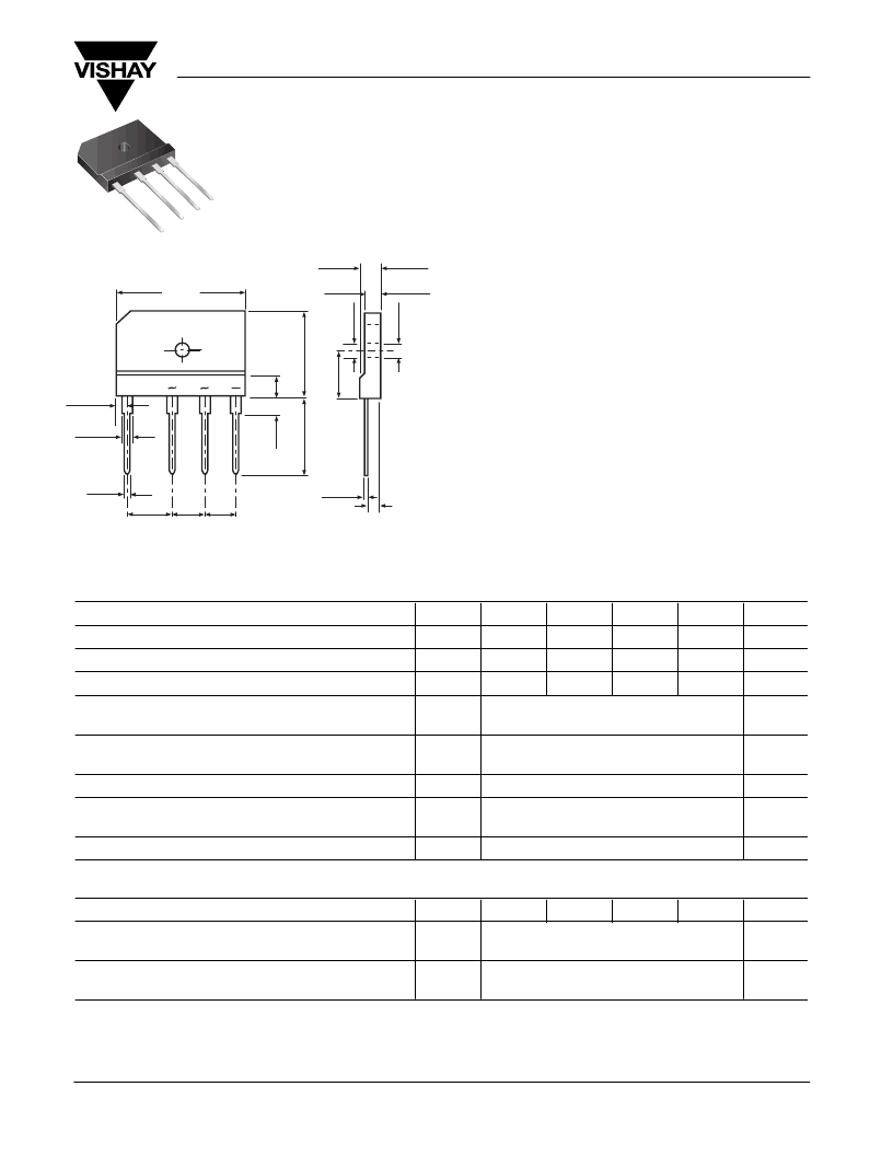
Case Style GSIB-5S
Dimensions in millimeters
Features
Plastic package has Underwriters Laboratory
Flammability Classification 94V-0
This series is UL listed under the Recognized
Component Index, file number E54214
High case dielectric strength of 1500 V
RMS
Ideal for printed circuit boards
Glass passivated chip junction
High surge current capability
Mechanical Data
Case:
5S Molded plastic body
Terminals:
Plated leads solderable per MIL-STD-750,
Method 2026
High temperature soldering guaranteed:
260°C/10 seconds, 0.375 (9.5mm) lead length,
5lbs. (2.3kg) tension
Mounting Position:
Any
(3)
Mounting Torque:
5 in-lbs max.
Weight:
0.26 oz., 7.0 g
Maximum Ratings & Thermal Characteristics
Ratings at 25°C ambient temperature unless otherwise specified.
Parameter
Symbol
GSIB620 GSIB640 GSIB660 GSIB680
Unit
Maximum repetitive peak reverse voltage
V
RRM
200
400
600
800
V
Maximum RMS voltage
V
RMS
140
280
420
560
V
Maximum DC blocking voltage
V
DC
200
400
600
800
V
Maximum average forward rectified
output current at
T
C
= 100°C
T
A
= 25°C
6.0
(1)
2.8
(2)
I
F(AV)
A
Peak forward surge current single sine-wave
superimposed on rated load (JEDEC Method)
I
FSM
180
A
Rating for fusing (t < 8.3ms)
I
2
t
120
A
2
sec
Typical thermal resistance per leg
R
θ
JA
R
θ
JC
22
(2)
3.4
(1)
°C/W
Operating junction and storage temperature range
T
J
, T
STG
–55 to +150
°C
Electrical Characteristics
Ratings at 25°C ambient temperature unless otherwise specified.
Parameter
Symbol
GSIB620 GSIB640 GSIB660 GSIB680
Unit
Maximum instantaneous forward voltage drop
per leg at 3.0A
V
F
0.95
V
Maximum DC reverse current at
rated DC blocking voltage per leg
T
A
= 25°C
T
A
= 125°C
10
250
I
R
μ
A
Notes:
(1) Unit case mounted on Al plate heatsink
(2) Units mounted on P.C.B. with 0.5 x 0.5" (12 x 12mm) copper pads and 0.375" (9.5mm) lead length
(3) Recommended mounting position is to bolt down on heatsink with silicone thermal compound for
maximum heat transfer with #6 screw
相關PDF資料 |
PDF描述 |
|---|---|
| GSIB680 | Glass Passivated Single-Phase Bridge Rectifier |
| GSIB6A20 | Glass Passivated Single-Phase Bridge Rectifier |
| GSIB6A40 | Glass Passivated Single-Phase Bridge Rectifier |
| GSIB6A60 | Glass Passivated Single-Phase Bridge Rectifier |
| GSIB6A80 | Glass Passivated Single-Phase Bridge Rectifier |
相關代理商/技術參數 |
參數描述 |
|---|---|
| GSIB660 | 制造商:Vishay Semiconductors 功能描述:BRIDGE RECTIFIER 6A 600V |
| GSIB660-E3/45 | 功能描述:橋式整流器 6.0 Amp 600 Volt RoHS:否 制造商:Vishay 產品:Single Phase Bridge 峰值反向電壓:1000 V 最大 RMS 反向電壓: 正向連續電流:4.5 A 最大浪涌電流:450 A 正向電壓下降:1 V 最大反向漏泄電流:10 uA 功率耗散: 最大工作溫度:+ 150 C 長度:30.3 mm 寬度:4.1 mm 高度:20.3 mm 安裝風格:Through Hole 封裝 / 箱體:SIP-4 封裝:Tube |
| GSIB660L-5700/45 | 制造商:Vishay Semiconductors 功能描述:2.8 A, 600 V, SILICON, BRIDGE RECTIFIER DIODE |
| GSIB680 | 制造商:VISHAY 制造商全稱:Vishay Siliconix 功能描述:Single-Phase Single In-Line Bridge Rectifiers |
| GSIB680 | 制造商:Vishay Semiconductors 功能描述:BRIDGE RECTIFIER 6A 800V |
發布緊急采購,3分鐘左右您將得到回復。