- 您現在的位置:買賣IC網 > PDF目錄385381 > HI7131CPL (INTERSIL CORP) 3 1/2 Digit, Low Power, High CMRR, LCD/LED Display-Type A/D Converters PDF資料下載
參數資料
| 型號: | HI7131CPL |
| 廠商: | INTERSIL CORP |
| 元件分類: | ADC |
| 英文描述: | 3 1/2 Digit, Low Power, High CMRR, LCD/LED Display-Type A/D Converters |
| 中文描述: | 1-CH 3-BIT DUAL-SLOPE ADC, PARALLEL ACCESS, PDIP40 |
| 封裝: | PLASTIC, DIP-40 |
| 文件頁數: | 13/21頁 |
| 文件大小: | 209K |
| 代理商: | HI7131CPL |
3-1838
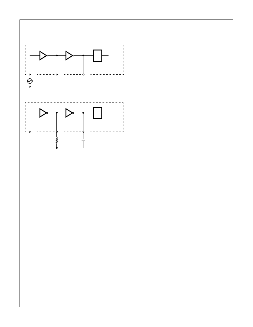
1. Figure 7A, an External Oscillator Driving OSC 1.
2. Figure 7B, an RC Oscillator Using All 3 Oscillator Circuit
Pins.
The oscillator output frequency is divided by 4 before it clocks
the rest of the digital section. Notice that there are 2 separate
frequencies which are referred to as; oscillator frequency
(f
OSC
) and clock frequency (f
CLK
) with the relation of:
To achieve maximum rejection of 60Hz pickup, the signal
integrate cycle should be a multiple of 60Hz. For 60Hz,
rejection oscillator frequencies of 120kHz, 80kHz, 60kHz,
48kHz, 40kHz, 33
1
/
3
kHz, etc. should be selected. For 50Hz
rejection, oscillator frequencies of, 100kHz, 66
2
/
3
kHz, 50kHz,
40kHz, etc. would be suitable. Note that 40kHz (2.5 read-
ings/sec) will reject both 50Hz and 60Hz (also 400Hz and
440Hz).
For the RC oscillator configuration the relationship between
oscillator frequency, R and C values are:
(R in Ohms and C in Farads.)
System Timing
As it has been mentioned, the oscillator output is divided by
4 prior to clocking the digital section and specifically, the
internal decade counters. The control logic looks at the
counter outputs and comparator output (see analog section)
to form the appropriate timing for 4 phases of conversion
cycle.
The total length of a conversion cycle is equal to 4000
counts and is independent of the input signal magnitude or
full scale range. Each phase of the conversion cycle has the
following length:
Auto-Zero Phase
100 counts in case an overrange is detected. 990 to 2990
counts for normal conversion. For those inputs which are less
than full scale, the deintegrate length is less than 2000 counts.
Those extra counts on deintegrate phase are assigned to
auto-zero phase to keep the conversion cycle constant.
Signal Integrate Phase
1000 counts, a fixed period of time. The time of integration
can be calculated as:
Deintegrate Phase
0 to 2000 counts, variable length phase depending on the
input voltage.
Zero Integrate Phase
10 counts in case of normal conversion. 900 counts in case
an overrange is detected.
Functional Considerations of Device Pins
COMMON Pin
The COMMON pin is the device internal reference generator
output.
The COMMON pin sets a voltage that is about 2.8V less
than the V+ supply rail. This voltage (V+ - V
COMMON
) is the
on-chip reference which can be used for setting converter
reference voltage.
Within the IC, the COMMON pin is tied to an N-Channel tran-
sistor capable of sinking up to 3mA of current and still keeping
COMMON voltage within the range. However, there is only 1
μ
A
of source current capability. The COMMON pin can be used as
a virtual ground in single supply applications when the external
analog signals need a reference point in between the supply
rails. If higher sink and source current capability is needed for
virtual ground a unity gain op-amp can be used as a buffer.
Differential Inputs (IN LO, IN HI)
The input can accept differential voltages anywhere within the
common mode range of the input amplifier, or specifically from
1V below the positive supply to 1V above the negative supply.
In this range, the system has a CMRR of 120dB (Typ).
However, care must be exercised to assure the integrator
output does not saturate. This is illustrated in Figure 8, which
shows how common mode voltage affects maximum swing on
the integrator output. Figure 8 shows the circuit configuration
during conversion. In this figure, common mode voltage is
considered as a voltage on the IN LO pin referenced to
(V+ - V-) / 2, which is usually the GND in a dual supply
system.
CLOCK
INTERNAL TO PART
40
39
38
TEST
÷
4
FIGURE 95A. EXTERNAL SIGNAL
CLOCK
INTERNAL TO PART
40
39
38
÷
4
R
C
FIGURE 95B. RC OSCILLATOR
FIGURE 95. CLOCK CIRCUITS
f
CLK
f
-------------
=
f
OSC
OSC
OSC
---------------------------------
≈
T
INT
1000
CLK
------------
4000
OSC
-------------
.
=
=
HI7131, HI7133
相關PDF資料 |
PDF描述 |
|---|---|
| HI7133 | 3 1/2 Digit, Low Power, High CMRR, LCD/LED Display-Type A/D Converters |
| HI7133CM44 | 3 1/2 Digit, Low Power, High CMRR, LCD/LED Display-Type A/D Converters |
| HI7133CPL | Power Resistor; Series:200; Resistance:4.5kohm; Resistance Tolerance: 5%; Power Rating:8W; Resistor Element Material:Ceramic; Temperature Coefficient:260 ppm; Leaded Process Compatible:No; Packaging:Bulk RoHS Compliant: No |
| HI7190IP | null24-Bit, High Precision, Sigma Delta A/D Converter |
| HI7190EVAL | null24-Bit, High Precision, Sigma Delta A/D Converter |
相關代理商/技術參數 |
參數描述 |
|---|---|
| HI7133 | 制造商:INTERSIL 制造商全稱:Intersil Corporation 功能描述:3 1/2 Digit, Low Power, High CMRR, LCD/LED Display-Type A/D Converters |
| HI7133 WAF | 制造商:Harris Corporation 功能描述: |
| HI7133CM44 | 制造商:Rochester Electronics LLC 功能描述:- Bulk |
| HI7133CM44S2324 | 制造商:Rochester Electronics LLC 功能描述:- Bulk |
| HI7133CPL | 制造商:Rochester Electronics LLC 功能描述:- Bulk 制造商:Harris Corporation 功能描述: |
發布緊急采購,3分鐘左右您將得到回復。