- 您現在的位置:買賣IC網 > PDF目錄385404 > HT82K94E (Holtek Semiconductor Inc.) USB Multimedia Keyboard Encoder 8-Bit MCU PDF資料下載
參數資料
| 型號: | HT82K94E |
| 廠商: | Holtek Semiconductor Inc. |
| 英文描述: | USB Multimedia Keyboard Encoder 8-Bit MCU |
| 中文描述: | 的USB多媒體鍵盤編碼器8位微控制器 |
| 文件頁數: | 11/44頁 |
| 文件大小: | 295K |
| 代理商: | HT82K94E |
第1頁第2頁第3頁第4頁第5頁第6頁第7頁第8頁第9頁第10頁當前第11頁第12頁第13頁第14頁第15頁第16頁第17頁第18頁第19頁第20頁第21頁第22頁第23頁第24頁第25頁第26頁第27頁第28頁第29頁第30頁第31頁第32頁第33頁第34頁第35頁第36頁第37頁第38頁第39頁第40頁第41頁第42頁第43頁第44頁
HT82K94E/HT82K94A
Rev. 1.00
11
November 22, 2005
During the execution of an interrupt subroutine, other in-
terrupt acknowledge signals are held until the RETI in-
struction is executed or the EMI bit and the related
interrupt control bit are set to 1 (if the stack is not full).
To return from the interrupt subroutine, RET or RETI
may be invoked. RETI will set the EMI bit to enable an in-
terrupt service, but RET will not.
Interrupts, occurring in the interval between the rising
edges of two consecutive T2 pulses, will be serviced on
the latter of the two T2 pulses, if the corresponding inter-
rupts are enabled. In the case of simultaneous requests
the following table shows the priority that is applied.
These can be masked by resetting the EMIbit.
No.
Interrupt Source
Priority Vector
a
USB interrupt
1
04H
b
Timer/Event Counter 0 overflow
2
08H
c
Timer/Event Counter 1 overflow
3
0CH
The Timer/Event Counter 0/1 interrupt request flag
(T0F/T1F), USB interrupt request flag (USBF), enable
Timer/Event Counter 0/1 interrupt bit (ET0I/ET1I), enable
USB interrupt bit (EUI) and enable master interrupt bit
(EMI)constituteaninterruptcontrolregister(INTC)which
is located at 0BH in the data memory. EMI, EUI, ETI are
usedtocontroltheenabling/disablingofinterrupts.These
bits prevent the requested interrupt from being serviced.
Once the interrupt request flags (TF, USBF) are set, they
willremainintheINTCregisteruntiltheinterruptsareser-
viced or cleared by a software instruction.
It is recommended that a program does not use the
CALL subroutine within the interrupt subroutine. Inter-
rupts often occur in an unpredictable manner or need to
be serviced immediately in some applications. If only one
stack is left and enabling the interrupt is not well con-
trolled, the original control sequence will be damaged
once the CALL operates in the interrupt subroutine.
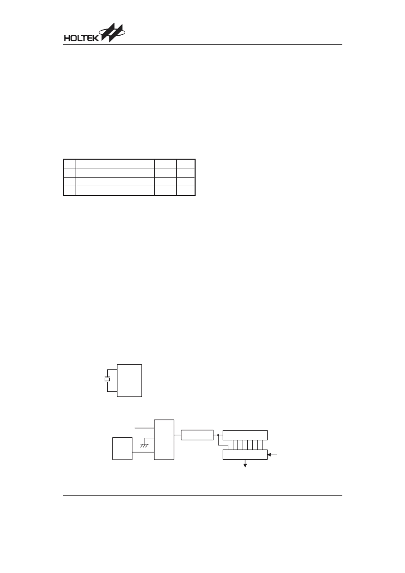
Oscillator Configuration
There is an oscillator circuits in the microcontroller.
This oscillator is designed for system clocks. The HALT
mode stops the system oscillator and ignores an exter-
nal signal to conserve power.
A crystal across OSC1 and OSC2 is needed to provide
the feedback and phase shift required for the oscillator.
No other external components are required. In stead of
a crystal, a resonator can also be connected between
OSC1 and OSC2 to get a frequency reference, but two
external capacitors in OSC1 and OSC2 are required.
The WDT oscillator is a free running on-chip RC oscilla-
tor, and no external components are required. Even if
the system enters the power down mode, the system
clock is stopped, but the WDToscillator still works within
a period of approximately 31 s. The WDT oscillator can
be disabled by ROM code option to conserve power.
Watchdog Timer
WDT
The WDT clock source is implemented by a dedicated
RC oscillator (WDT oscillator), or instruction clock (sys-
tem clock divided by 4), determines the ROM code op-
tion. This timer is designed to prevent a software
malfunction or sequence from jumping to an unknown
location with unpredictable results. The Watchdog
Timer can be disabled by ROM code option. If the
Watchdog Timer is disabled, all the executions related
to the WDT result in no operation.
Once the internal WDT oscillator (RC oscillator, nor-
mally with a period of 31 s/5V) is selected, it is first di-
vided by 256 (8-stage) to get the nominal time-out
period of 8ms/5V. This time-out period may vary with
temperatures, VDD and process variations. By invoking
the WDT prescaler, longer time-out periods can be real-
ized. Writing data to WS2, WS1, WS0 (bits 2, 1, 0 of the
WDTS) can give different time-out periods. If WS2,
WS1, and WS0 are all equal to 1, the division ratio is up
to 1:128, and the maximum time-out period is 1s/5V. If
the WDT oscillator is disabled, the WDT clock may still
come from the instruction clock and operates in the
same manner except that in the HALT state the WDT
may stop counting and lose its protecting purpose. In
this situation the logic can only be restarted by external
logic. The high nibble and bit 3 of the WDTS are re-
served for user s defined flags, which can only be set to
10000 (WDTS.7~WDTS.3).
!
(
,
< ) *
6 5 =
(
+
(
!
,
0 5 =
(
6 5
5 (
+
(
5
+
- +
"
,
+
Watchdog Timer
!
, (
!
, ,
System Oscillator
相關PDF資料 |
PDF描述 |
|---|---|
| HT82K94E_07 | USB Multimedia Keyboard Encoder 8-Bit MCU |
| HT82K95AE | USB Multimedia Keyboard Encoder 8-Bit MCU |
| HT82K95EE | USB Multimedia Keyboard Encoder 8-Bit MCU |
| HT82K95A | USB Multimedia Keyboard Encoder 8-Bit MCU |
| HT82K95E | USB Multimedia Keyboard Encoder 8-Bit MCU |
相關代理商/技術參數 |
參數描述 |
|---|---|
| HT82K94E_07 | 制造商:HOLTEK 制造商全稱:Holtek Semiconductor Inc 功能描述:USB Multimedia Keyboard Encoder 8-Bit MCU |
| HT82K95A | 制造商:HOLTEK 制造商全稱:Holtek Semiconductor Inc 功能描述:USB Multimedia Keyboard Encoder 8-Bit MCU |
| HT82K95AE | 制造商:HOLTEK 制造商全稱:Holtek Semiconductor Inc 功能描述:USB Multimedia Keyboard Encoder 8-Bit MCU |
| HT82K95E | 制造商:HOLTEK 制造商全稱:Holtek Semiconductor Inc 功能描述:USB Multimedia Keyboard Encoder 8-Bit MCU |
| HT82K95EE | 制造商:HOLTEK 制造商全稱:Holtek Semiconductor Inc 功能描述:USB Multimedia Keyboard Encoder 8-Bit MCU |
發布緊急采購,3分鐘左右您將得到回復。