- 您現在的位置:買賣IC網 > PDF目錄385405 > HT86576 (Holtek Semiconductor Inc.) Voice Synthesizer 8-Bit MCU PDF資料下載
參數資料
| 型號: | HT86576 |
| 廠商: | Holtek Semiconductor Inc. |
| 英文描述: | Voice Synthesizer 8-Bit MCU |
| 中文描述: | 語音合成器8位微控制器 |
| 文件頁數: | 24/39頁 |
| 文件大小: | 368K |
| 代理商: | HT86576 |
第1頁第2頁第3頁第4頁第5頁第6頁第7頁第8頁第9頁第10頁第11頁第12頁第13頁第14頁第15頁第16頁第17頁第18頁第19頁第20頁第21頁第22頁第23頁當前第24頁第25頁第26頁第27頁第28頁第29頁第30頁第31頁第32頁第33頁第34頁第35頁第36頁第37頁第38頁第39頁
HT86XXX
Rev. 1.70
24
May 6, 2004
The WDT overflow under normal operation will initialize
a chip reset and set the status bit TO . Whereas in
the HALT mode, the overflow will initialize a warm re -
set only the PC and SP are reset to zero. To clear the
contents of the WDT (including the WDT prescaler),
three methods are adopted; external reset (external re-
set(alowleveltoRES),softwareinstructions,oraHALT
instruction. The software instruction is CLR WDT and
execution of the CLR WDT instruction will clear the
WDT.
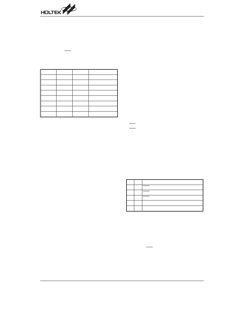
WS2
WS1
WS0
Division Ratio
0
0
0
1:1
0
0
1
1:2
0
1
0
1:4
0
1
1
1:8
1
0
0
1:16
1
0
1
1:32
1
1
0
1:64
1
1
1
1:128
WDTS Register
Power Down
HALT
The HALT mode is initialized by a HALT instruction and
results in the following:
The system oscillator will be turned off but the WDT os-
cillatorkeepsrunning(iftheWDToscillatorisselected).
The contents of the on chip RAM and registers remain
unchanged.
WDT and WDT prescaler will be cleared and recount
again.
All I/O ports maintain their their original status.
The PD flag is set and the TO flag is cleared.
The system can leave the HALT mode by means of an
external reset, an interrupt, an external falling edge sig-
nal on port A or a WDT overflow. An external reset
causes a device initialization and the WDToverflow per-
forms a warm reset . By examining the TO and PD
flags, the reason for the chip reset can be determined.
The PD flag is cleared when the system powers-up or
executes the CLR WDT instruction, and is set when
the HALT instructionisexecuted.TheTOflagissetifa
WDT time-out occurs, and causes a wake-up that only
resets the PC and SP. The other maintain their original
status.
The port A wake-up and interrupt methods can be con-
sidered as a continuation of normal execution. Each bit
in port A can be independently selected to wake up the
device by a mask option. Awakening from an I/O port
stimulus, the program will resume execution of the next
instruction. If awakening from an interrupt, two se-
quences may happen. If the related interrupt is disabled
or the interrupt is enabled by the stack is full, the pro-
gram will resume execution at the next instruction. If the
interrupt is enabled and the stack is not full, the regular
interrupt response takes place.
Once a wake-up event occurs, it takes 1024 system
clock period to resume normal operation. In other
words, a dummy cycle period will be inserted after a
wake-up. If the wake-up results from an interrupt ac-
knowledge, the actual interrupt subroutine will be de-
layed by one more cycle. If the wake-up results in next
instruction execution, this will be executed immediately
after a dummy period is finished. If an interrupt request
flag is set to 1 before entering the HALT mode, the
wake-up function of the related interrupt will be dis-
abled. To minimize power consumption, all I/O pins
should be carefully managed before entering the HALT
status.
Reset
There are 3 ways in which a reset can occur:
RES reset during normal operation
RES reset during HALT
WDT time-out reset during normal operation
The WDT time-out during HALT is different from other
chip reset conditions, since it can perform a warm re -
set thatresetsonlythePCandSP,leavingtheothercir-
cuits in their original state. Some registers remain un-
changed during any other reset conditions. Most
registers are reset to their initial condition when the re-
set conditions are met. By examining the PD flag and
TO flag, the program can distinguish between different
chip resets .
TO
PD
RESET Conditions
0
0
RES reset during power-up
u
u
RES reset during normal operation
0
1
RES wake-up HALT
1
u
WDT time-out during normal operation
1
1
WDT wake-up HALT
Note: u stands for unchanged
To guarantee that the system oscillator has started and
stabilized, the SST (System Start-up Timer) provides an
extra-delay of 1024 system clock pulses after a system
power up or when awakening from a HALT state.
When a system power up occurs, the SST delay is
added during the reset period. But when the reset co-
mes from the RES pin, the SST delay is disabled. Any
wake-up from HALT will enable the SST delay.
相關PDF資料 |
PDF描述 |
|---|---|
| HT86R192 | Voice Synthesizer 8-Bit OTP MCU |
| HT86R384 | Voice Synthesizer 8-Bit OTP MCU |
| HT86XXX | 8-Bit Voice Synthesizer MCU |
| HT8950 | Voice Modulator |
| HT8955 | Voice Echo |
相關代理商/技術參數 |
參數描述 |
|---|---|
| HT8658 | 制造商:HOLTEK 制造商全稱:Holtek Semiconductor Inc 功能描述:Voice Recorder (DRAM) |
| HT8658A | 制造商:未知廠家 制造商全稱:未知廠家 功能描述:Solid-State Recorder |
| HT8658B | 制造商:未知廠家 制造商全稱:未知廠家 功能描述:Solid-State Recorder |
| HT8659 | 制造商:HOLTEK 制造商全稱:Holtek Semiconductor Inc 功能描述:Voice Recorder (DRAM) |
| HT8659A | 制造商:未知廠家 制造商全稱:未知廠家 功能描述:Solid-State Recorder |
發布緊急采購,3分鐘左右您將得到回復。